Wiring guide – Honeywell PRESTIGE THX9000 User Manual
Page 4
Prestige
TM
Installation Guide
4
69-2057EFS—03
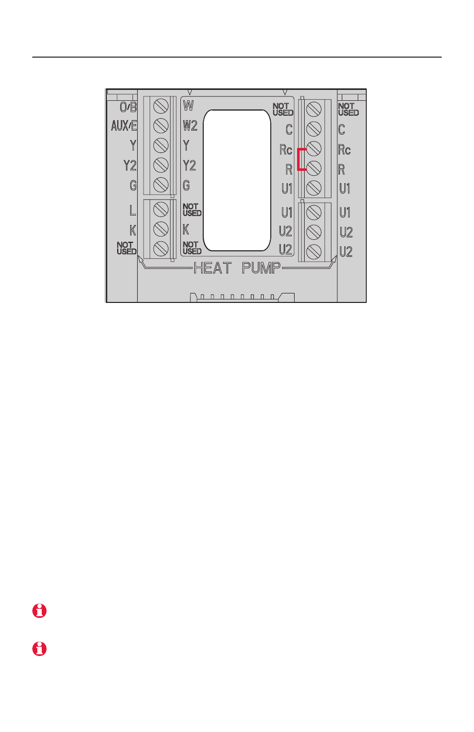
Wiring guide
See detailed wiring guides for specific system types on following pages.
Conventional Terminal Letters:
C Common wire from secondary side of
cooling transformer.
Rc Cooling power. Connect to secondary
side of cooling system transformer.
R
Heating power. Connect to seconary
side of heating system transformer.
W Heat relay (stage 1).
W2 Heat relay (stage 2).
Y
Compressor contactor (stage 1).
Y2 Compressor contactor (stage 2).
G
Fan relay.
K
THP9054 connection
(see note below)
U1/U1 Configuarable IAQ relay for humidi-
fier, dehumidifier, or vent
U2/U2 Configuarable IAQ relay for humidi-
fier, dehumidifier, or vent
Heat Pump Terminal Letters:
C
Common wire from secondary side of
cooling system transformer.
Rc Cooling power. Connect to secondary
side of cooling system transformer.
R
Heating power. Connect to secondary
side of heating system transformer.
O/B Changeover valve for heat pumps.
Aux/E Auxiliary/Emergency heat relay.
Y
Compressor contactor (stage 1).
Y2 Compressor contactor (stage 2).
G
Fan relay.
L
Heat pump reset (powered continuously
when System is set to Em Heat; system
monitor when set to Heat, Cool or Off).
K
THP9054 connection
(see note below)
U1/U1 Configuarable IAQ relay for humidi-
fier, dehumidifier, or vent
U2/U2 Configuarable IAQ relay for humidi-
fier, dehumidifier, or vent
Note: Use the K terminal in place of the Y and G terminals to provide full fan and compressor
control though a single wire. The K terminal must be connected to the THP9045 Wiresaver
module (see page 14). The K terminal can not be used in heat-only applications.
Note: Do not connect wires to terminals marked “Not Used.”
MCR29860