Hoshizaki KM-2500SWH3 User Manual
Page 33
33
8) Reconnect the black float switch connector, then replace the control box cover in its
correct position.
9) Move the control switch to the "ICE" position. Replace the insulation panel and the
front panel in their correct positions, then turn on the power supply. After 1 minute, the
1-minute fill cycle should end and the initial harvest cycle should begin. If the initial
harvest cycle begins, the float switch is good and the check is complete. If the initial
harvest cycle does not begin, continue to step 10.
10) Turn off the power supply.
11) Remove the front panel.
12) Move the control switch to the "OFF" position.
13) Remove the control box cover.
14) Disconnect the black float switch connector from the control board BLACK K5 connector.
15) Check for continuity across the float switch leads. With the water tank full, the float
switch should be closed. If the float switch is closed and the icemaker will not switch
from the 1-minute fill cycle to the initial harvest cycle, replace the control board.
If the float switch is open, confirm that the water tank is full. If the tank is not full, check
the water supply, water filters, and inlet water valve. If the tank is full, follow the steps in
"IV.D.2. Float Switch Cleaning." After cleaning the float switch, check it again. Replace if
necessary.
2. Float Switch Cleaning
Depending on local water conditions, scale may build up on the float switch. Scale on the
switch can cause the float to stick. In this case, the float switch should be cleaned.
1) Turn off the power supply.
2) Remove the front panel and move the control switch to the "OFF" position.
3) Remove the insulation panel, then remove the cap located on the front bottom part of
the ice dropping hole. Drain the water tank.
4) Replace the cap in its correct position. Be
careful not to cross thread it.
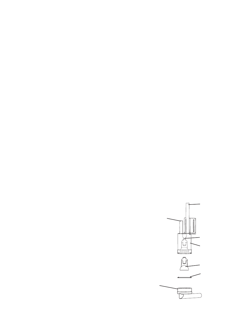
5) Disconnect the vent tube and the flush
tube from the top of the float switch, then
remove the float switch assembly from the
mounting bracket and remove the rubber
boot from the bottom of the float switch
assembly. See Fig. 2.
6) Remove the retainer rod from the bottom of
the float switch assembly, then remove the
float. Be careful not to bend the retainer rod
excessively when removing it.
Float
Float Switch
Housing
Rubber Boot
and Hose
Retainer Rod
Flush
Vent
Shaft
Fig. 2