Control board layout, E" control board – Hoshizaki KM-2500SWH3 User Manual
Page 16
16
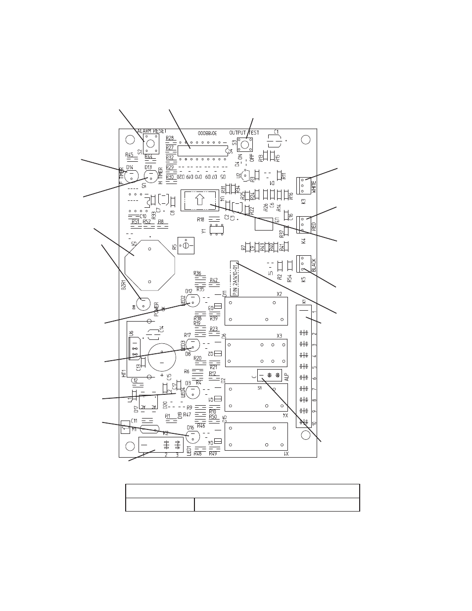
"E" Control Board
1. Control Board Layout
"E" Control Board
Part Number
2A1410-01 (factory);
2A1410-02 (service)
• "OUTPUT TEST" Button
(used to test relays on control board)
• WHITE K3 Connector
Harvest Control
(thermistor)
• RED K4 Connector
Open (not connected)
• Microprocessor
(control board
revision level
indicated by last 2
digits on label)
• BLACK K5 Connector
Float Switch
• Part Number
• K1 Ten-Pin Connector
Pins #1 through #10
#1, 9 Magnetic Contactor (CR)
Fan Motor-Remote (FMR)
#2 Hot Gas Valve (HGV)
#3 Fan Motor (FM)
Liquid Line Valve (LLV)
#4 Pump Motor (icemaking)
#5 Pump Motor (pump-out)
#6 Inlet Water Valve (WV)
#7, 10 Component Power
Supply
#8 Open
• Switch for "C" Control Board
and "ALPINE" Control Board
(service boards only)
• "ALARM RESET" Button
•
"F TIMER"
Freeze Timer LED
• S4 Dip Switch
• "H TIMER"
Harvest Backup
Timer LED
• Alarm Buzzer
• "Power OK" LED
(red) (lights when
power is supplied to
the control board)
• LED 2 (X2 Relay)
Hot Gas Valve (HGV)
Fan Motor (FM) (FM
off when LED on)
• LED 3 (X3 Relay)
Pump Motor (PM)
(on at pump-out only)
• LED 4 (X4 Relay)
Inlet Water Valve (WV)
• LED 1 (X1 Relay)
Compressor
(Comp)
Fan Motor-Remote
(FMR)
• K2 Connector
Transformer
• Relay LEDs (4)
(indicate which relays
are energized as
listed below)