Hitachi L300P User Manual
Page 99
“B” Group: Fine-Tuning Functions
Configur
ing Dr
iv
e
P
a
ra
meters
3–30
The torque developed in a motor is directly proportional to the current in the windings, which is
also proportional to the heat generated (and temperature, over time). Therefore, you must set
the thermal overload threshold in terms of current (amperes) with parameter B012. The range is
50% to 120% of the rated current for each inverter model. If the current exceeds the level you
specify, the inverter will trip and log an event (error E5) in the history table. The inverter turns
the motor output OFF when tripped. Separate settings are available for the second and third
motors (if applicable), as shown in the table below.
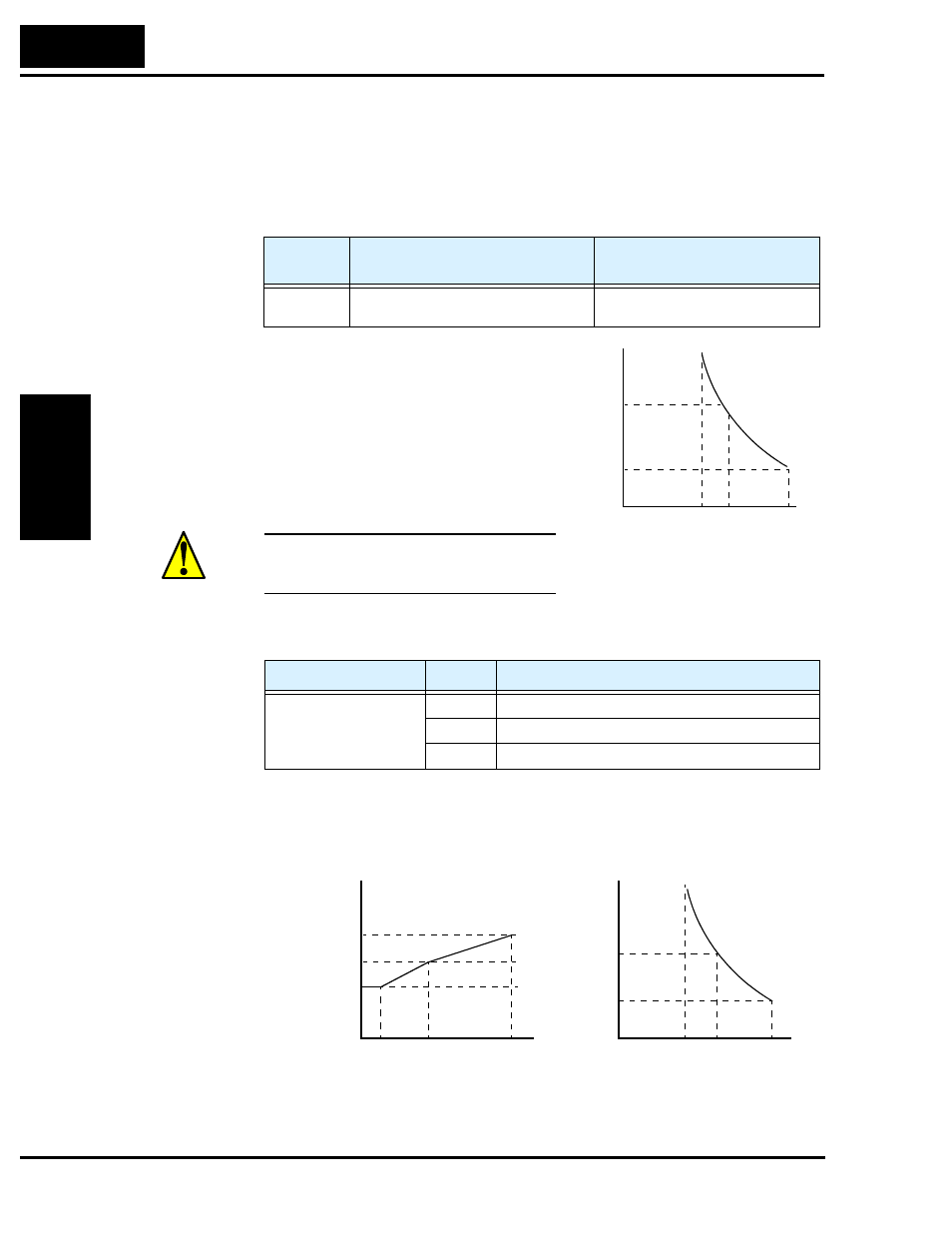
For example, suppose you have inverter model
L300P-110LFU2. The rated motor current is
44A. The setting range is (0.2 * 44) to (1.2 *44),
or 8.8A to 52.8A. For a setting of B012 = 44A
(current at 100%) and output frequency = 60Hz,
the figure to the right shows the curve.
The electronic thermal characteristic adjusts the
way the inverter calculates thermal heating,
based on the type of load connected to the motor,
as set by parameter B013.
CAUTION: When the motor runs at lower
speeds, the cooling effect of the motor’s internal
fan decreases.
The table below shows the torque profile settings. Use the one that matches your load.
Reduced Torque Characteristic – The left graph below shows the effect of the reduced torque
characteristic curve. For example, at 20Hz, the output current level to cause overheating in a
fixed time period is reduced by a factor of 0.8. The right graph below shows the reduced trip
current levels in those conditions for given trip times.
Function
Code
Function/Description
Data or Range
B012 / B212 Electronic thermal setting (calculated
within the inverter from current output)
Range is 0.2 * rated current to
1.2 * rated current
Function Code
Data
Function/Description
B013 / B213
00
Reduced torque
01
Constant torque
02
Free-setting
Trip current at 60 Hz
Trip
time (s)
60
116%
0.5
0
51
52.8
66
120%
150%
A
Trip
time (s)
60
92.8%
0.5
0
40.8
42.2
52.8
96%
120%
A
x 1.0
x 0.6
0
5
20
60
Hz
x 0.8
Reduced trip current at 20 Hz
Trip current
reduction
factor