Hitachi L300P User Manual
Page 174
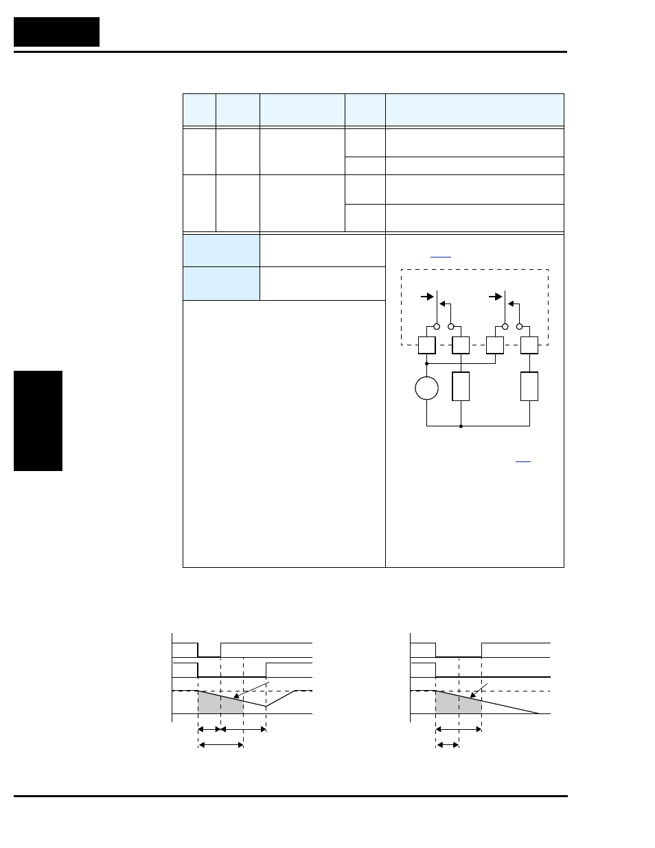
Using Intelligent Output Terminals
Oper
ations
a
nd Moni
tor
ing
4–44
In the following examples, t
0
= instantaneous power failure time, t
1
= allowable under-voltage /
power failure time (B002), and t
2
= retry wait time (B003).
Opt.
Code
Symbol
Function Name
Output
State
Description
08
IP
Instantaneous
Power Failure
ON
when the inverter detects a loss of input
power
OFF
when the inverter has input power
09
UV
Under-voltage
condition
ON
when the inverter input power is less than
the specified input range
OFF
when the inverter input power is within
the voltage specification
Valid for
outputs:
11, 12, AL0 – AL2
Required
settings:
B001, B002, B003, B004,
B005, B007
Notes:
• If an over-voltage or over-current trip occurs
during the deceleration and an instantaneous
power failure error (E16) is displayed the
inverter goes into free-run stop. In this case
make the deceleration time longer.
• When connecting control power supply
terminal [Ro]-[To] to the DC bus [P]-[N], an
under-voltage may be detected at power-off
and cause a trip. If this is undesirable, set
B004 to 00 or 02.
• Frequency matching: The inverter reads the
motor RPM and direction. If this speed is
higher than the matching setting (B007), the
inverter waits until they are equal and then
engages the output to drive the motor
(example 3). If the actual motor speed is less
than the restart frequency setting, the inverter
waits for t
2
(value in B003) and restarts from
0 Hz (example 4). The display shows
“
oooo
” during an actual frequency
matching event.
UV
IP
See I/O specs on page
.
Inverter output terminal circuit
12C
12A
11C
11A
24VDC
L
L
Example (requires output configuration—
see page
):
+
–
Power supply
Inverter output
Motor
frequency
After waiting for t
2
seconds when t
0
< t
1
; restart
Example 1: Power failure within allowed limits; resume
Example 2: Power failure longer than limits; trip
t
0
t
1
t
2
Power supply
Inverter output
Motor
frequency
t
0
t
1
Inverter trips when t
0
> t
1
Free-run
Free-run
t
t