Reference materials – Heat & Glo Fireplace BRAVO 704-902 User Manual
Page 48
Heat & Glo • Bravo • 704-902 Rev. F • 10/08
48
K
L
B
C
D
E
F
G
H
Ø J
I
M
N
O
P
A
GAS LINE
ACCESS
ELECTRICAL
ACCESS
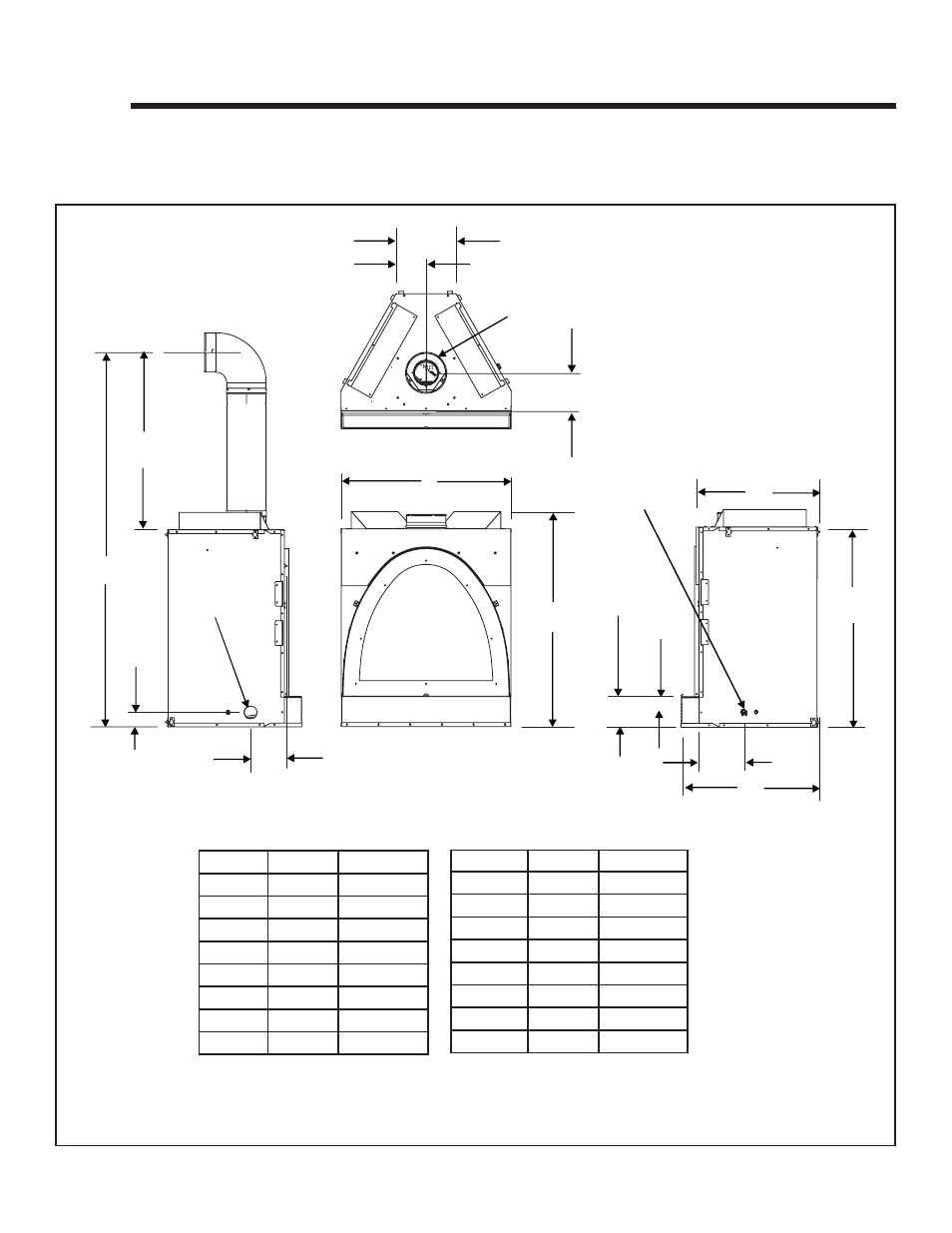
Figure 16.1 Appliance Dimensions
Location Inches
Millimeters
I*
8-1/4
209
J
8
203
K
12-1/8
308
L
6
154
M
46-3/4
187
N
86-3/4
2203
O
2-7/8
74
P*
7-3/8
188
Location Inches
Millimeters
A
34-3/8
875
B
43-1/2
1104
C
6-1/8
157
D
3
77
E*
9-3/8
237
F*
27-3/4
706
G
40
1015
H*
24-3/4
628
*All dimensions in the front to back direction are taken
from the 1/2 inch standoffs on the front face of the unit.
16
16
Reference Materials
A. Appliance Dimension Diagram
Dimensions are actual appliance dimensions. Use for reference only. For framing dimensions and clearances refer to Section 3.