Brick replacement instructions, Baffle removal & installation, 3100-i act wood insert – Hearth and Home Technologies 3100-I User Manual
Page 19
Page 19
September 1, 2008
3100-I ACT WOOD INSERT
R
250-638D
BAFFLE REMOVAL & INSTALLATION
NOTE: The baffle in the 3100-I ACT Insert is 2700° Fiber Board. Removing hardware exposed to combustion processes can
be frustrating. If your reason for removing the baffle is simply to clean the chimney, you have alternatives which will save time
and effort. Call a qualified chimney sweep or an authorized Quadra-Fire dealer for details.
1. Remove all ash from the firebox, and extinguish all hot embers before disposal into a metal container.
2. Remove the ceramic blanket from above the baffle.
3. With a 3/16” allen wrench, remove the 2 front manifold tube retainer bolts on the air channel under the end of the front tubes.
NOTE: Soak the bolts with penetrating oil for at least 15 minutes before trying to remove them.
See Figure 19B.
4. To remove the manifold tubes, slide the tube to one side until one end is out of its hole. Then, while lifting that end of the fiber
board, pull the tube up over the air channel and out of the hole at the other end.
NOTE: When replacing the manifold tubes,
be sure the tube with the larger holes is placed in the front for your insert to operate properly.
5. Slide fiber board forward to front of stove, tilt down and slide to the door. Tilt to one side and slide through door.
See Figure 19C.
6. Keep the fiber board baffle tilted as you lift it out of the door.
7. To install the fiber board baffle, repeat steps 2 through 4 in reverse. Be sure that the fiber board and ceramic
blanket are pushed back fully.
Figure 19C
Figure 19B
Allen wrench
on retainer bolt
First tube has larger holes
Allen
wrench on
retainer
bolt.
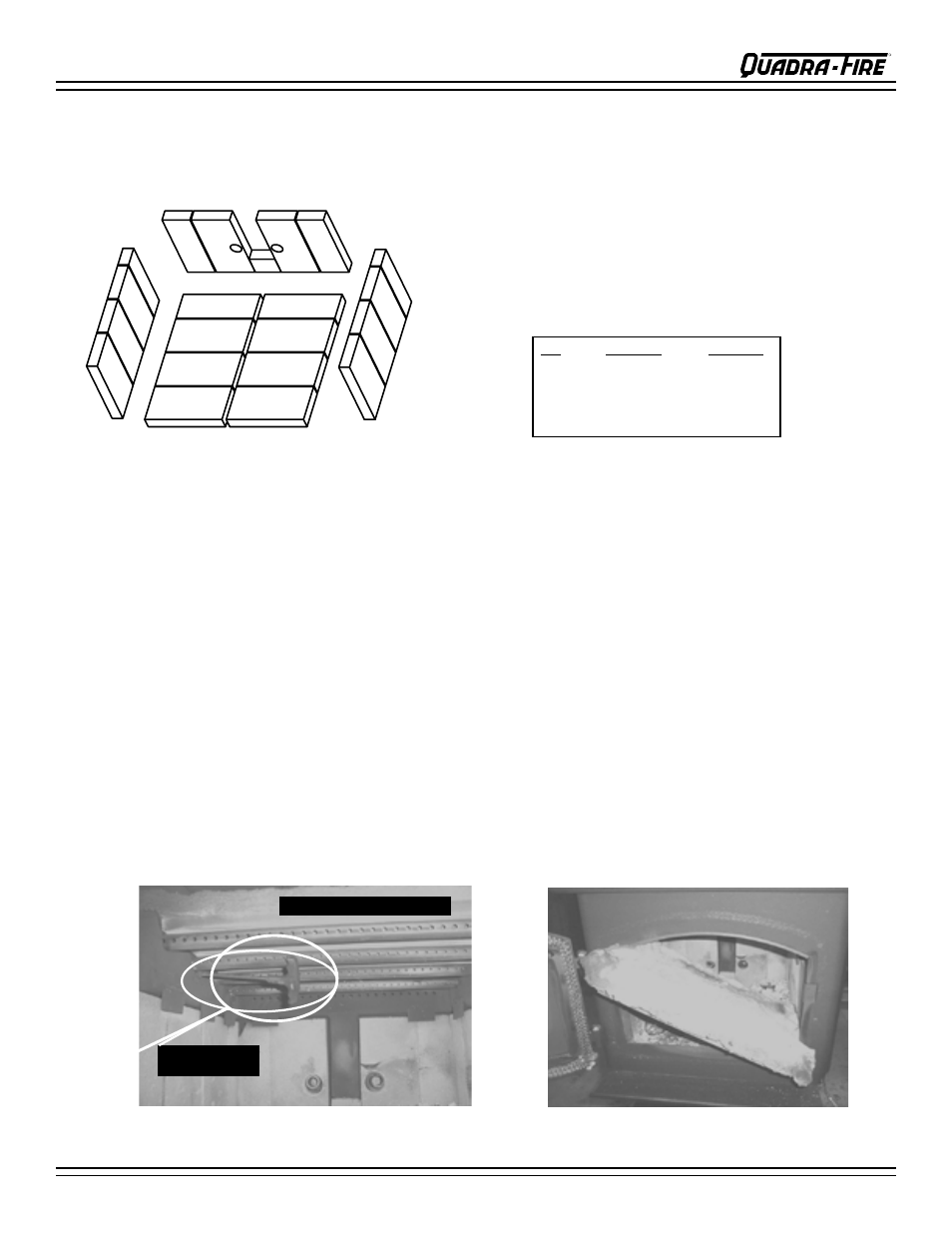
BRICK REPLACEMENT INSTRUCTIONS
The firebox of your Quadra-Fire 3100-I ACT Insert is lined with high quality firebrick which has exceptional insulating proper-
ties. There is no need for a grate, simply build a fire on the firebox of your insert.
1. Remove all old brick and ash from unit.
2. Remove new brick set from box and lay out to diagram as shown in
Figure
19A.
3. Lay bottom bricks in unit.
4. Install rear bricks on the top of the bottom bricks. Slide top of bricks under
clip on back of firebox wall and push bottom of brick back.
5. Install side bricks. Slide top of brick under clips on side of firebox and
push the bottom of the brick until it is flush with the side of the unit.
Nbr
Brick Size
Qty in Set
1
9 x 4.5 x 1.25”
12
2
9 x 4.5 x 1.25”
2
3
9 x 3.25 x 1.25”
4
4
9 x 2.25 x 1.25”
2
5
3 x 2.25 x 1.25”
1
Use Part Number 832-0550 when ordering individual brick and provide the
brick dimensions or copy this page and mark desired brick and take it your
authorized dealer.
Figure 19A
1
1
1
1
1
1
1
1
1
1
1
1
3
3
5
3
3
4
4
Brick Set Part Number: 831-1830