Hitachi HUS157336EL3600 User Manual
Page 24
Drawing No. Sheet No. Revision 5
K6602906
24/46
2003/6/12
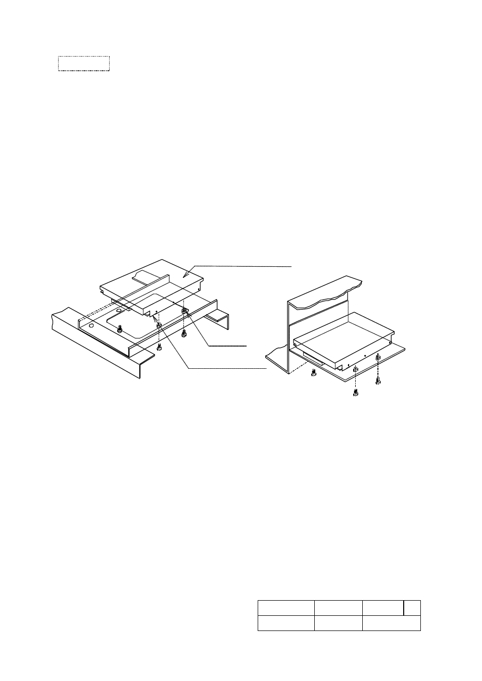
7.2 Mounting of the drive
1. Mount the drive with four 6-32 UNC screws. (Screw's torque : 0.588
to
0.784 N·m)
2. Mounting holes (A1,A2,B1,B2,B3) are available for mounting.(See figure 8.3)
It is recommended that the 4 holes, (A1,A2 or B1,B3 on figure 8.3), be used for mounting to
keep the proper space between mounting holes.
3. Maximum penetration of the screw is 3.8 mm.
4. Keep a clearance of 3 millimeters from the PCB parts side and the HDA's upper surface for
proper cooling air ventilation. (See figure 8.2)
5. The mounting chassis’s weight shall be more than 2 kg, and the stiffness of mounting
chassis shall be more than 196,000 N/m. The stiffness of 4 mounting points shall not be un-
balanced.
6. The HDA enclosure is connected to the DC ground on PCB in HDA electrically.
If electrical insulation of the HDA is preferred when it is mounted to the mounting chassis,
insert an insulator between the HDA enclosure and the mounting chassis.
Good case
Bad case
HDA upper surface
PCB parts side
spacer
Figure 7.2 Example for mounting
Caution