Installation instructions, Inst alla tion instructions, Cooktop installation (cont.) – GE Profile 30 Inch Electric Cooktop Owners Guide User Manual
Page 24
24
49-2001160 Rev. 0
Installation Instructions
COOKTOP INSTALLATION (Cont.)
INST
ALLA
TION INSTRUCTIONS
18. MAKING ELECTRICAL
CONNECTIONS (Cont.)
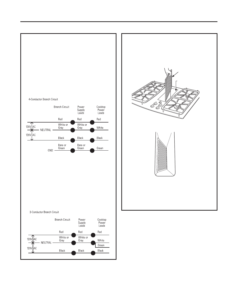
4-Conductor Branch Circuit
When connecting the cooktop to a 4-conductor
circuit, connect the red leads of the cooktop and the
power supply to the branch circuit red lead; connect
the black leads to each other. Connect the cooktop
white lead to the power supply and branch circuit
neutral leads, which are white or gray. Ground
the unit by connecting the green conductor of the
cooktop to the bare or green leads of the power
supply and branch circuit (ground leads).
Three-conductor branch circuit connection
• When installing in existing construction built prior
to January 1, 1996, and if permitted by local
codes:
3-Conductor Branch Circuit
When connecting cooktop to a 3-conductor circuit,
connect the red leads of the cooktop and the power
supply to the branch circuit red lead; connect the
black leads to each other. Connect the green and
white leads of the cooktop to the power supply and
branch circuit neutral leads, which are white or gray.
20. INSTALL DOWNDRAFT FILTER
AND VENT GRILLE
'RQRWRSHUDWHWKHYHQWZLWKRXWWKHILOWHULQSODFH
• Place the filter diagonally through the vent
opening.
• Make sure it rests, at an angle, on the supports in
the vent opening.
• Carefully place the vent grille onto the gasket on
the downdraft opening.
CHECK OPERATION OF DOWNDRAFT
7XUQWKHYHQWIDQVSHHGFRQWUROWR+,0('DQG
LO to make sure all speeds operate correctly.
Vent Filter
Vent
Chamber