Viewing chassis information, Front panel information, Viewing chassis information -2 – Enterasys Networks FN 100 User Manual
Page 18: Front panel information -2
The FN100 Chassis View
2-2
Viewing Chassis Information
Viewing Chassis Information
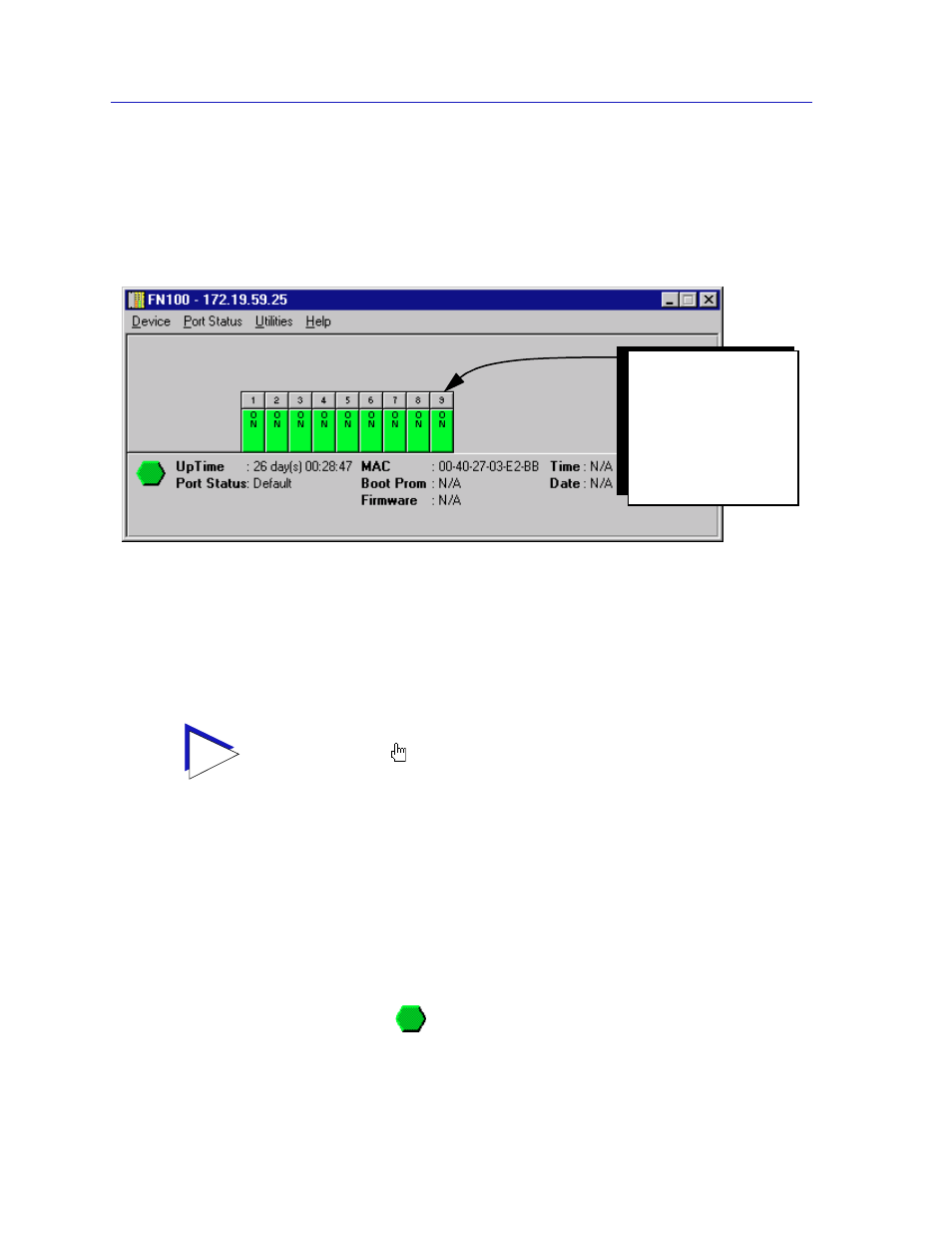
The FN100 Chassis View window (
Figure 2-1
) provides a graphic representation
of the FN100, including a color-coded port display which immediately informs
you of the current configuration and status of the switch and its ports.
Figure 2-1. FN100 Chassis View Window
By clicking in designated areas of the chassis graphical display (as detailed later
in this chapter), or by using the menu bar at the top of the Chassis View window,
you can access all of the menus that lead to more detailed device- and port- level
windows.
Front Panel Information
The areas above and below the main port display area provide the following
device information:
IP
The Internet Protocol address assigned to the FN100 appears in the title bar of the
Chassis View window; this field will display the IP address you have used to
create the FN100 icon. IP addresses are assigned via Local Management.
Connection Status
This color-coded area indicates the current state of communication between
NetSight Element Manager and the FN100.
TIP
When you move the mouse cursor over a management “hot spot” the cursor icon will
change into a “hand”
to indicate that clicking in the current location will bring up a
management option.
On an 8-port FN100, the
network management
port is represented as
port 9. On a 16-port
FN100, the network
management port will be
represented as port 17.