Notes for tables 6 and 7, Lanning, Va, s – Emerson Series 610 User Manual
Page 47: Ingle, Odule, Ystems, D appendix a, To appendix a, E appendix a . be sure environment, Appendix a
Site Pla
n
n
in
g
Da
ta
, 10
00kV
A, Sin
g
le-Mod
u
le Sys
te
m
s
43
A
PPENDIX
A - S
ITE
P
LANNING
D
ATA
, 1000
K
VA, S
INGLE
-M
ODULE
S
YSTEMS
1. Nominal rectifier AC input current (considered continuous) is based on full
rated output load. Maximum current includes nominal input current and
maximum battery recharge current (considered noncontinuous). Continuous
and noncontinuous current limits are defined in NEC 100. Maximum input
current is controlled by current limit setting, which is adjustable. Values
shown for maximum settings are 125% of nominal input current. Standard
factory setting is 115%.
2. Nominal AC output current (considered continuous) is based on full rated
output load. Maximum current includes nominal output current and
overload current for 10 minutes.
3. Bypass AC input current (considered continuous) is based on full rated
output load.
4. Feeder protection (by others in external equipment) for rectifier AC input
and bypass AC input is recommended to be provided by separate overcurrent
protection devices.
5. UPS output load cables must be run in separate conduit from input cables.
6. Power cable from module DC bus to battery should be sized for a total
maximum 2.0 volt line drop (power cable drop plus return cable drop as
measured at the module) at maximum discharge current.
7. Grounding conductors to be sized per NEC 250-95. Neutral conductors to be
sized for full capacity—per NEC 310-16, Note 10—for systems with 4-wire
loads and half capacity for systems with 3-wire loads.
8. Rectifier AC Input: 3-phase, 3-wire, plus ground
AC Output to Load: 3-phase, 3- or 4-wire, plus ground
Bypass AC Input: 3-phase, 4-wire, plus ground (3-wire in some circumstances)
Module DC Input from Battery: 2-wire (positive and negative), plus ground
9. All wiring is to be in accordance with National and Local Electrical Codes.
10. Minimum overhead clearance is 2 ft. (0.6m) above the UPS.
11. Top or bottom cable entry through removable access plates. Cut plate to suit
conduit size.
12. Control wiring and power cables must be run in separate conduits. Control
wiring must be stranded tinned conductors.
13. 4% maximum reflected input harmonic current and 0.92 lagging input power
factor at full load with optional 12-pulse rectifier and optional input filter.
14. UPS module will be shipped in sections. Reconnect shipping splits according
to drawings supplied with the equipment.
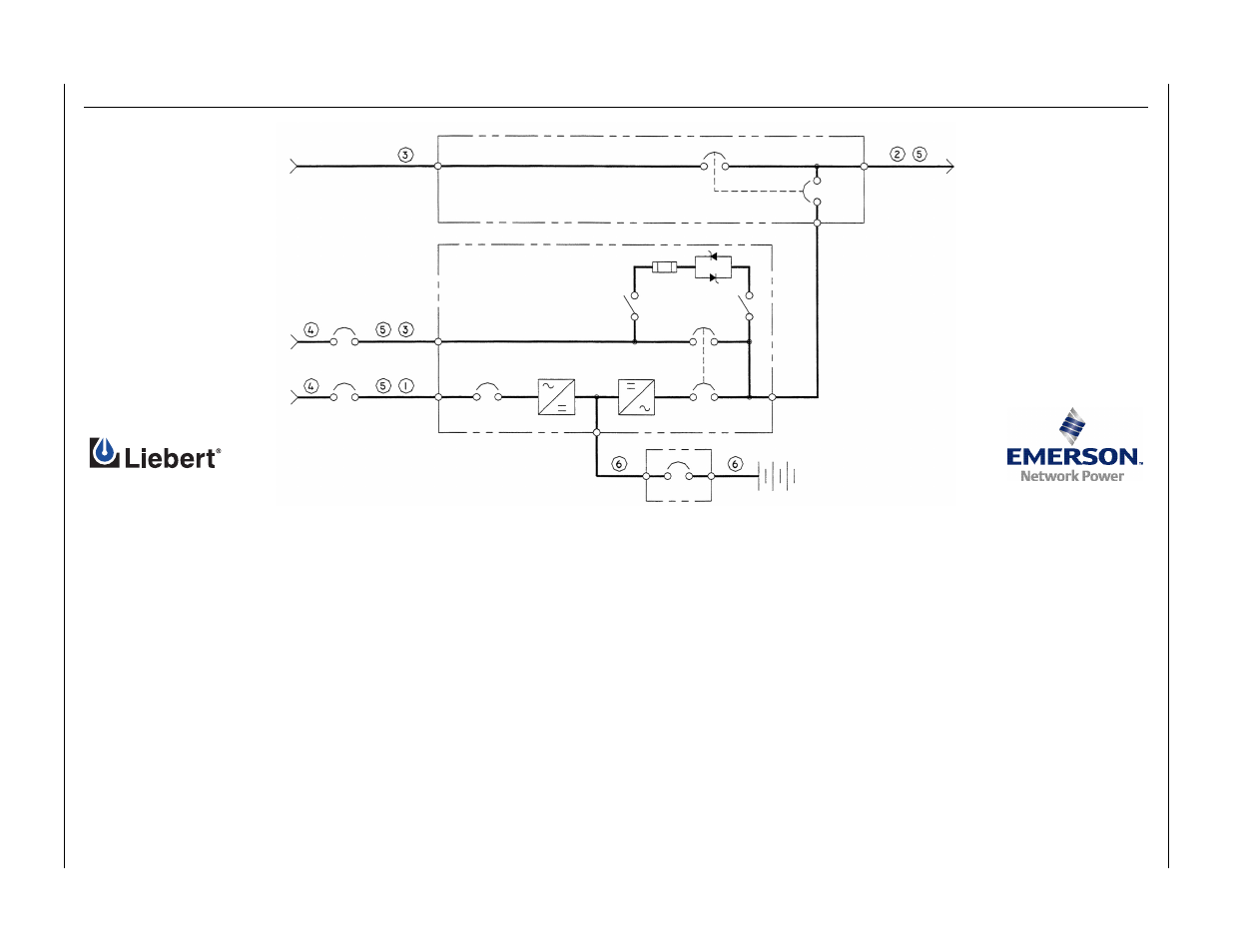
Maintenance bypass switchgear
AC output
to load
Battery
MBD
UOB
SBB
MIB
MBB
UPS module
Bypass
AC input
Rectifier
AC input
CB1