Figure 8 power single-line diagrams, Figure 8, Power single-line diagrams – Emerson Series 610 User Manual
Page 25
Wiring Considerations
21
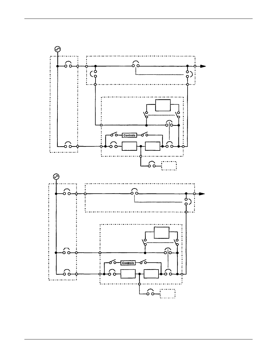
Figure 8
Power single-line diagrams*
* These configurations are for illustrative purposes only. They represent only a sample of the possible
configurations. Refer to the submittals supplied with your order for more information or for order-specific details.
Two-breaker maintenance bypass switchboard
MBFB
BIB
MBB
MIB
UPS module
Static
switch
disconnect
Static
bypass
switch
Bypass CB
Output CB
Battery
Main input
switchgear
RIB
Rectifier/
charger
Inverter
Input
CB
Control power
MBD
Critical load
AC output
Three-breaker maintenance bypass switchboard
BFB
BIB
MBB
MIB
Critical load
AC output
UPS module
Static
switch
disconnect
Static
bypass
switch
Bypass CB
Output CB
Battery
Main input
switchgear
RIB
Rectifier/
charger
Inverter
Input
CB
Control power
MBD