Signal generator, Vca gain – Ashly mXa-1502 12-Channel 4-Zone DSP Mixer-Amplifier User Manual
Page 19
boost because one of the more common
uses for parametric filters is to dramatically
cut, or "notch out", very narrow frequencies
(low bandwidth) in order to eliminate system
feedback problems.
Every instance of a parametric EQ filter has a
center frequency selected. Each filter's center
frequency is adjustable from 20Hz to 2000Hz
in 1/96 octave steps. Carefully sweeping a
narrow bandwidth filter through a problem
feedback area, with just a slight boost, is a
quick way to find the exact frequency causing
trouble. Once the offensive frequency has been
found, cut the filter's level, and the adjust the
bandwidth as narrow as possible while still
eliminating the feedback problem.
Bandwidth is adjustable from about 1/64
octave to four octaves, and the lower the
bandwidth, the less audible the filter action will
be. Finding the problem frequency is relatively
easy, but finding the best combination of cut
and bandwidth takes a little practice. Again
it is well worth the time getting comfortable
with the notching procedure, so that problems
can be quickly addressed with a sufficient but
minimal amount of correction.
Shelving EQ Filters
1st order filters use a gentle 6dB per octave
slope, while 2nd order filters use a 12dB per
octave slope for a more pronounced boost or
cut. All shelving filters have a boost/cut range
of +/- 15dB and frequency range from 20Hz
through 20kHz. Shelving filters are most useful
as broad tone controls to boost or cut the high
end or low end of an audio signal's frequency
content. Because they affect a wider spectrum
of audio, they are not as suitable for feedback
control as parametric filters.
All-Pass Filters
The all-pass option is a 2nd order all-pass filter
which provides a -180 degree phase shift at
the corner frequency. At very high frequencies
the phase delay approaches -360 degrees.
All-pass filters may be used to add frequency
dependent phase shift or phase delay to
the audio signal path. It does not produce a
measurable effect on the magnitude response
of the signal.
Signal Generator
The signal generator creates pink noise, white
noise or a sine wave output.
When a signal generator is placed in an input
signal chain and turned on, audio input for that
channel becomes disabled.
When placed in an output signal chain and
turned on, the mixer signal selected for that
output channel becomes disabled.
White noise is randomly generated broadband
noise.
Pink noise is bandwidth-limited 20Hz - 20kHz
to contain equal energy in any octave (-6 dB
per octave low-pass filtered).
The sine wave has adjustable frequency. All
three signal types can be generated at any level
from -50dBu to +20dBu.
Signal Generator Parameters
Signal Type
: Pink noise, white noise, or sine
wave
Frequency
: Frequency of signal to be
generated (sine wave only).
Level
: RMS level of signal generated.
Bypass
: Turns off generated signal and allows
audio signal to pass through.
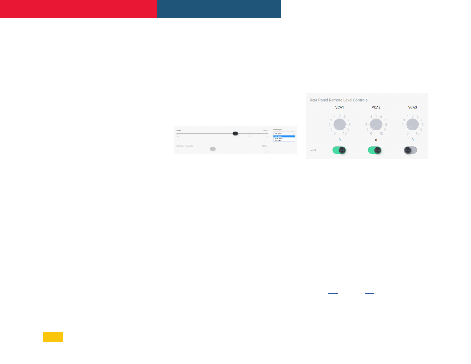
VCA Gain
The three back-panel VCA (voltage controlled
amplifier) input pins are used to remotely
control the level of assigned inputs or outputs
using a simple potentiometer circuit.
In order to use the VCA inputs, one or more VCA
gain blocks must first be placed in the signal
chain, then assigned to VCA inputs 1-3. A
single VCA input pin can control multiple VCA
Gain blocks, as long as they are all assigned in
software to the same VCA input pin.
Use the Ashly
or equivalent to send
a variable DC voltage to any of the three
. The current position of each
potentiometer is shown in the software.
Individual VCA inputs can be enabled or
disabled.
See sec.
for more details.
19
mXa-1502 • Operating Manual
Ashly AquaControl™ Software