Quick start guide — rgb 201 r xi , cont’d, Step 8, Step 9 – Extron Electronics RGB 201 User Manual
Page 6: Step 10, Switch position switch position
RGB 201 Rxi Universal Interface • Quick Start Guide
Quick Start Guide — RGB 201 Rxi, cont’d
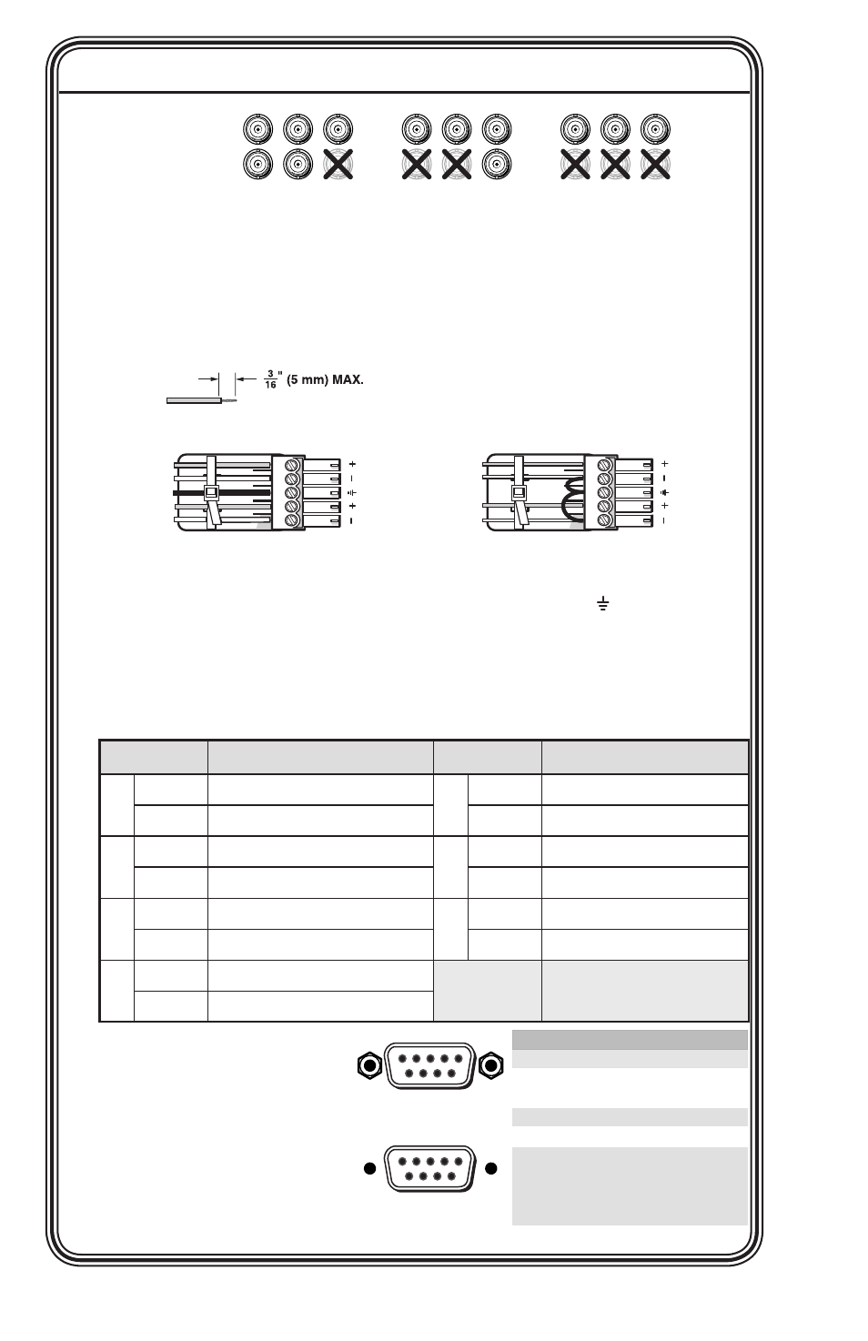
Pin
RS-232
Function
1
—
2
TX
Transmit data (-)
3
RX
Receive data (+)
4
—
5
Gnd
Signal ground
6
—
7
—
—
8
—
—
9
—
—
—
—
—
Female
5
1
9
6
Male
1
5
6
9
RGBHV
R
H
G
V
B
S
RGBS
R
G
S
B
V
H
S
RGsB
RsGsBs
R
G
B
V
H
Step 8
Audio output
— Connect an audio device, such as powered
speakers, to this 3.5 mm, 5-pole captive screw connector for balanced
or unbalanced audio output. The figure below shows how to wire
the captive screw audio connector.
Balanced Audio
Tip
Ring
Tip
Ring
L
R
Sleeves
Do not tin the wires!
Unbalanced Audio
Tip
Sleeve
Sleeve
Tip
L
R
C
Connect the sleeve(s) to ground ( ). Connecting
the sleeve(s) to a negative (-) terminal will damage
audio output circuits.
Step 9
DIP switches
— Configure the rear panel DIP switches as shown:
Switch
Position
Switch
Position
1
Up
DDSP, no sync processing
5
Up
Mono on left channel
Down
ADSP
Down
Stereo audio
2
Up
RGsB or RsGsBs output
6
Up
LCD backlight off
Down
RGBHV or RGBS output
Down
LCD backlight on
3
Up
Serration pulses
7
Up
ID bits 4 & 11 grounded
Down
No Serration pulses
Down
ID bits unterminated
4
Up
Narrow V sync pulse
8
Spare
Down
Wide V sync pulse
Step 10
Remote connector
—
Connect an RS-232 device
to this connector for
remote control. See