Installation and operation, cont’d, Figure 2-5 — rack mounting – Extron Electronics RGB 201 User Manual
Page 22
RGB 201 Rxi Universal Interface • Installation and Operation
Installation and Operation, cont’d
2-10
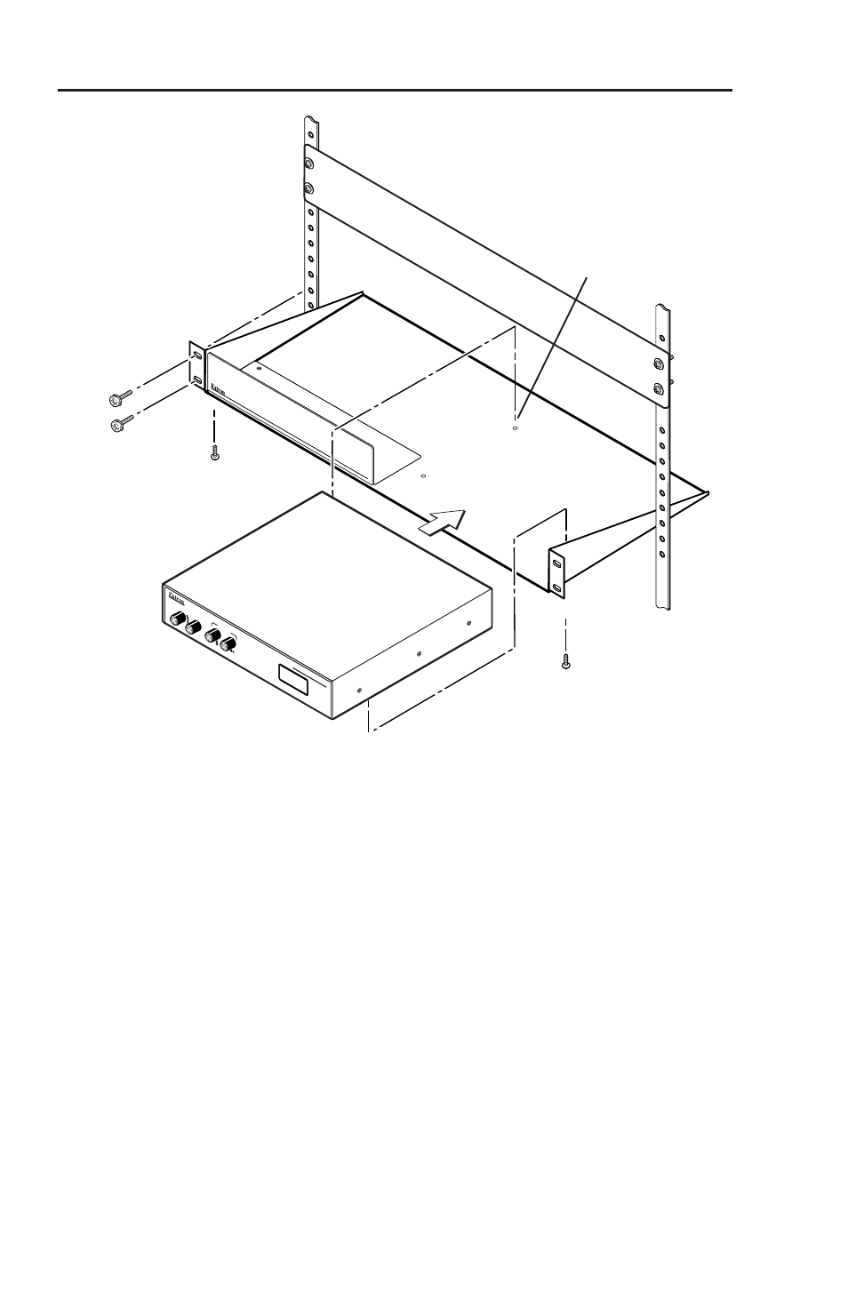
(2) 4-40 x 3/16" Screws
Use 2 mounting holes on
opposite corners
False Front panel
uses 2 front holes
RG
B 201R
xi
BOO
ST
LEVE
L
CON
TRO
L
PEAK
WITH
ADS
P
TM
CEN
TERIN
G
Figure 2-5 — Rack mounting
3
.
Secure the interface to the rack shelf with the two provided
4-40 x 1/8" machine screws. Insert the screws from the
underside of the shelf, and securely fasten them through
diagonally opposite corners as shown in the illustration
above.
4
.
Fasten the false front panel (provided with the rack shelf)
to the unoccupied side of the rack (as shown above), or
install a second half-rack-width device in that side by
repeating steps 1 through 3.
5
.
Secure the rack shelf to the rack using four 10-32 x 3/4"
bolts. Insert the bolts through #10 beveled washers, then
through the holes in the rack ears.