Installation and operation, cont’d, Figure 2-8 — wiring the audio output connector, Dip switches in this chapter – Extron Electronics RGB 201 User Manual
Page 24
RGB 201 Rxi Universal Interface • Installation and Operation
Installation and Operation, cont’d
2-12
d
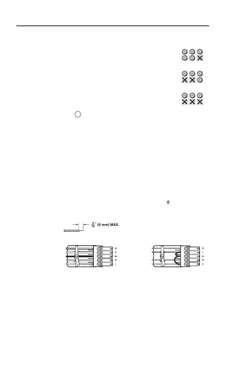
BNC output connectors — Connect a coaxial cable between the
display (projector or monitor) and these rear panel
BNC connectors.
For RGBHV (separate H and V sync) output,
connect the cables to five BNCs.
For RGBS (composite sync), connect the cables to
four BNCs.
For RGsB (sync on green, SOG) and RsGsBs (sync
on all
), connect the cables to three BNCs. Also
select the SOG option on the rear panel DIP switch
, Dip switches in this chapter.
e
Audio output connector — Connect an audio
device, such as powered speakers, to this 3.5 mm, 5-pole captive
screw connector for balanced or unbalanced audio output.
Figure 2-8 shows how to wire the captive screw audio connector.
The connector is included with the interface, but you must
obtain the cable. Insert the wires into the appropriate openings
in the captive screw connector. Tighten the screws on top to
fasten the wires.
C
Wiring the audio incorrectly can damage the audio
output circuits.
Connect the sleeve(s) to ground ( ). Connecting
the sleeve(s) to a negative (-) terminal will damage
audio output circuits.
Balanced Audio
Tip
Ring
Tip
Ring
L
R
Sleeves
Do not tin the wires!
Unbalanced Audio
Tip
Sleeve
Sleeve
Tip
L
R
Figure 2-8 — Wiring the audio output connector
RGBHV
R
H
G
V
B
S
S
RGBS
R
G
S
B
V
H
RGsB
RsGsBs
R
G
B
V
H