About the delay dials – Roland VC-1-DL Bi-Directional SDI/HDMI Video Converter with Delay and Frame Sync User Manual
Page 24
24
Setting the Operation Mode
MODE SW 6/7
This specifies the audio channels assigned to signals from the AUDIO OUT connectors.
Combinations of 6 and 7 specify the assigned channels as described below.
6
OFF
7
OFF
Channels 1 and 2 assigned
6
ON
7
OFF
Channels 3 and 4 assigned
6
OFF
7
ON
Channels 5 and 6 assigned
6
ON
7
ON
Channels 7 and 8 assigned
MODE SW 8
This specifies the enabled video source.
OFF
SDI input is enabled
ON
HDMI input is enabled
MODE SW 9
This specifies the type of 3G-SDI output coming out from the SDI OUT connector.
* The signal type of SDI IN is detected automatically.
OFF
Output with Level A mapping structure
ON
Output with Level B mapping structure
MODE SW 10
This specifies the control mode.
* This also enables/disables the AUTO OFF function (p. 13).
OFF
Mode is controlled by switches 1-9..
ON
The unit operates according to the settings in the internal memory (Set with VC-1
RCS software)
You can carry out detailed settings and save to unit’s internal memory using the
dedicated remote control software, the VC-1 RCS (p. 26).
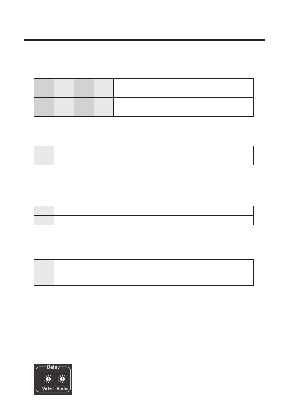
About the Delay Dials
These set the amount of delay for video and audio. You can set the amount of delay
independently for video and audio, in a range of 0 to 9 fields (0 to 4.5 frames) for each.
* When there is input to the REF IN connector, the delay caused by the frame-synchronizer
operation is added to the amount you have set.
fig.delay-dial.eps