Command entry formats, Mnet modbus command structure – ProSoft Technology MVI71-MNET User Manual
Page 33
Module Configuration
MVI71-MNET ♦ PLC Platform
User Manual
Modbus TCP/IP Interface Module
ProSoft Technology, Inc.
Page 33 of 109
June 23, 2009
Command Entry Formats
The following table shows the structure of the configuration data necessary for
each of the supported commands.
MNET MODBUS Command Structure
Column
#
1 2 3 4
5
6 7
8 9 10
Function
Code
Enable
Code
Internal
Address
Poll
Interval
Time
Count Swap
Code
IP
Address
Serv
Port
Slave
Node
Function
Code
Device
Modbus
Address
fc1 Code
Register
1/10th
Seconds
Count 0
IP
Address
Port # Address
1
Register
fc2 Code
Register
1/10th
Seconds
Count 0
IP
Address
Port # Address
2
Register
fc3 Code
Register
1/10th
Seconds
Count Code IP
Address
Port # Address
3
Register
fc4 Code
Register
1/10th
Seconds
Count Code IP
Address
Port # Address
4
Register
fc5 Code
Register
1/10th
Seconds
Count 0
IP
Address
Port # Address
5
Register
fc6 Code
Register
1/10th
Seconds
Count 0
IP
Address
Port # Address
6
Register
fc15 Code
Register
1/10th
Seconds
Count 0
IP
Address
Port # Address
15
Register
fc16 Code
Register
1/10th
Seconds
Count Code IP
Address
Port # Address
16
Register
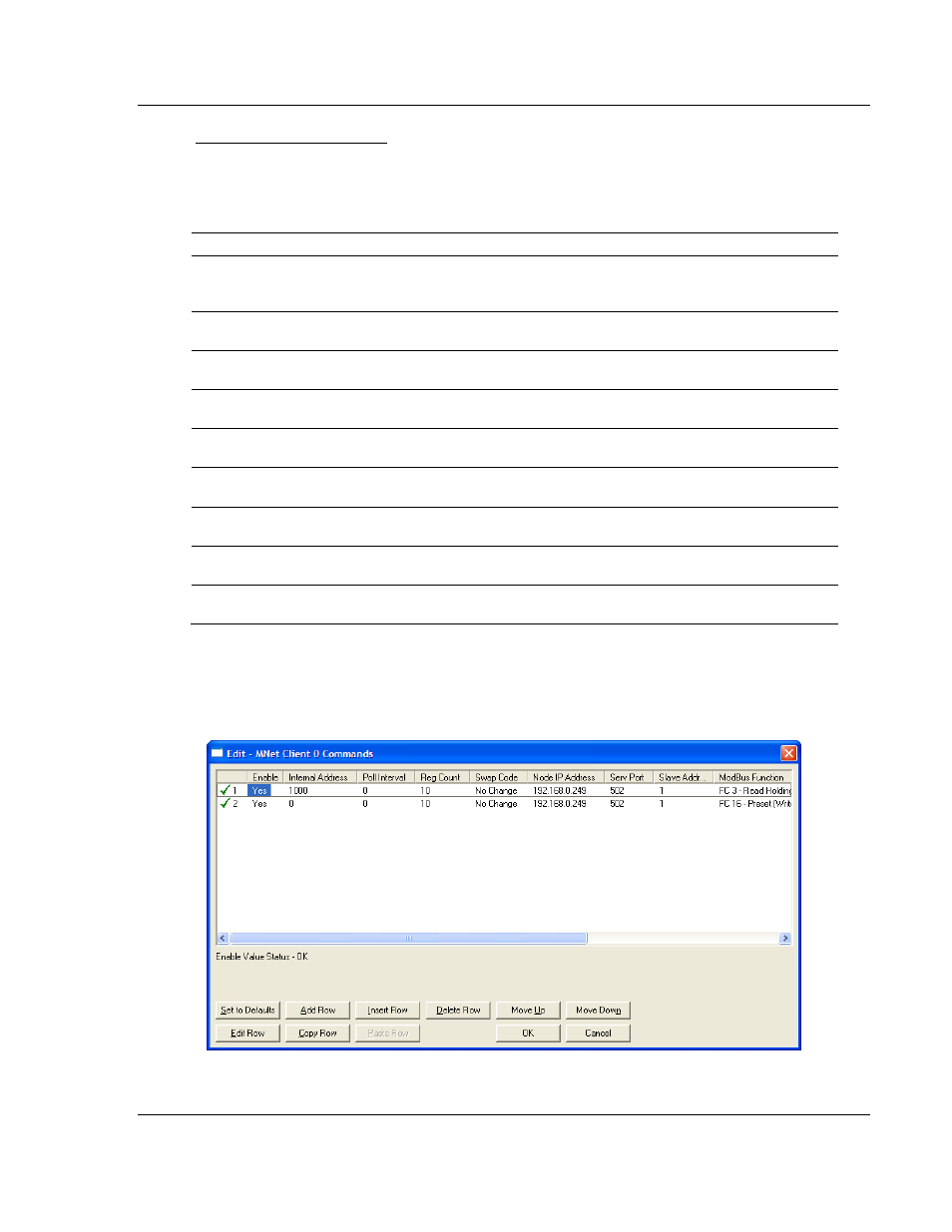
The first part of the record is the Module Information, which relates to the ProLinx
module and the second part contains information required to interface to the
Server device.
Command list example: