Hardware installation, 1 hardware description, 1 olt front panel – PLANET EPL-2000 User Manual
Page 10
User’s Manual of EPL-2000
2. HARDWARE INSTALLATION
This section describes the hardware features and installation of the GEPON OLT on the desktop or rack mount. For easier
management and control of the GEPON OLT, familiarize yourself with its display indicators and ports. Front panel illustrations in
this chapter display the unit LED indicators. Before connecting any network device to the GEPON OLT, please read this chapter
completely.
2.1 Hardware Description
2.1.1 OLT Front Panel
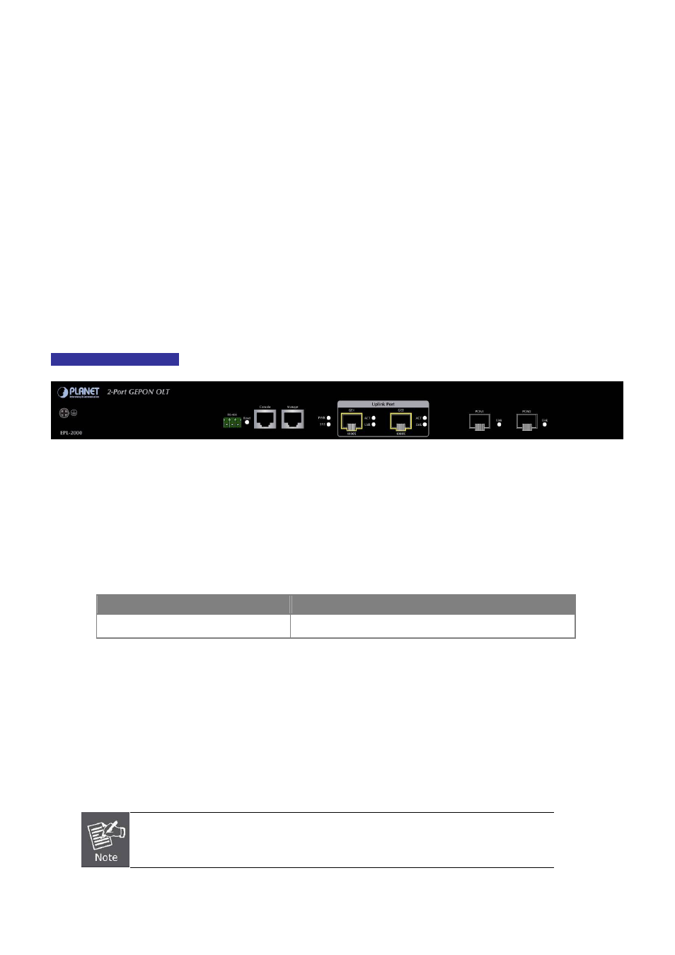
The unit front panel provides a simple interface monitoring the OLT.
Figure 2-1
shows the front panel of the GEPON OLT.
EPL-2000 Front Panel
Figure 2-1
EPL-2000 Front Panel
■ RS-485 and RJ45 Console Connector
This is just for Manufacturer Technical Use
■ Reset Button
The reset button is designed for rebooting the GEPON OLT without turning off and on the power. The following is the
summary table of reset button functions
:
Reset Button Pressed and Released
Function
System reboot
Reboot the GEPON OLT
■ Management Port
10/100BASE-TX Copper, RJ45 Twisted-[pair: Up to 100 meters
■ Gigabit SFP Uplink Slots
1000BASE-SX/LX mini-GBIC slot, SFP (Small Form Factor Pluggable) transceiver module: From 550 meters (multi-mode
fiber), up to 10/30/50/70/120 kilometers (single-mode fiber).
GE1 & GE2 Gigabit SFP uplink slots support 1000Mbps Forced Mode only. The remote
Gigabit switch or media converter’s SFP port must support 1000Mbps Forced Mode as well.
10