Table 1, Jt1a1 port 0 port 7 – Avago Technologies MegaRAID SAS 0260CV-4i User Manual
Page 6
Page 6
|
July 2011
MegaRAID SAS 9260CV-4i and SAS 9260CV-8i RAID Controller Quick Installation Guide
Installing the RAID Controller
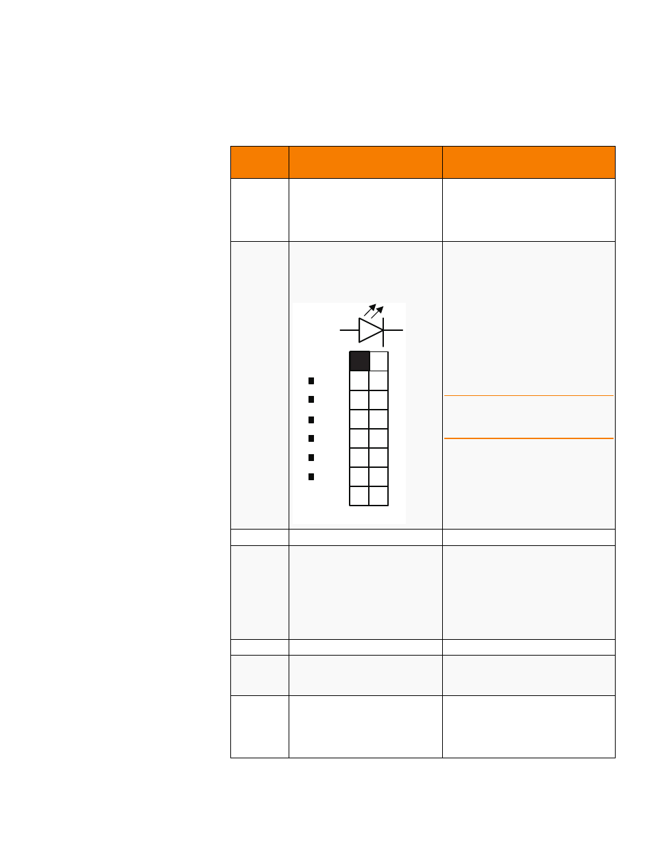
Table 1:
Jumpers and Connectors
Jumper/
Connector
Type
Description
J5A1
Board-to-board mezzanine
connector
Non-volatile memory module interface
The RAID controller is attached directly to
the
CVFM01
non-volatile memory
module using the J5A1 board-to-board
mezzanine connector.
JT1A1
LED Locate and Fault Indication
header
Ports 3-0
Ports 7-4
2x8-pin header
Connects to an LED array that indicates
whether a drive is in a fault condition.
There is one LED per port. When lit, each
LED indicates that the corresponding
drive has failed or is in the
Unconfigured-Bad state.
The LEDs function in a direct-attach
configuration (there are no SAS
expanders). Direct attach is defined as a
maximum of one drive connected directly
to each port.
NOTE: This is a 2x4 pin header on the
SAS 9260CV-4i RAID controller, for
ports 3-0.
JT1A2
LSI Internal use header
Reserved for LSI internal use.
JT1A3
SBR Firmware Recovery header
2-pin header
The SBR FW recovery header is used when
SBR corruption is suspected. Installing the
jumper allows the unit to boot while
bypassing the SBR information. You can
then reprogram the SEEPROM using
external utility software. No jumper is
present for normal operation.
JT1A4
Serial UART header
Reserved for LSI internal use.
JT1B1
SEP Enclosure Support header
3-pin header
Used for connection to the Port0
enclosure.
JT1B2
RAID Key Socket
2-pin header
The RAID Key socket is used when a
feature upgrade requires the use of a
modular RAID Key to be installed to
activate the feature.
JT1A1
PORT 0
PORT 7
+v e
- v e
a
k