4 physical characteristics, 6 lsisas9200-16e hba characteristics, 1 memory – Avago Technologies SAS 9200-8e Host Bus Adapter User Manual
Page 17: 2 leds, 3 connectors, Figure 6, Lsisas9212-4i4e board, Layout, Lsisas9200-16e hba characteristics
LSI Corporation
- 17 -
PCI Express to 6Gb/s Serial Attached SCSI (SAS) Host Bus Adapters User Guide
May 2013
Host Bus Adapter Characteristics
Characteristics of the LSI 6Gb/s HBAs
3.1.5.4
Physical Characteristics
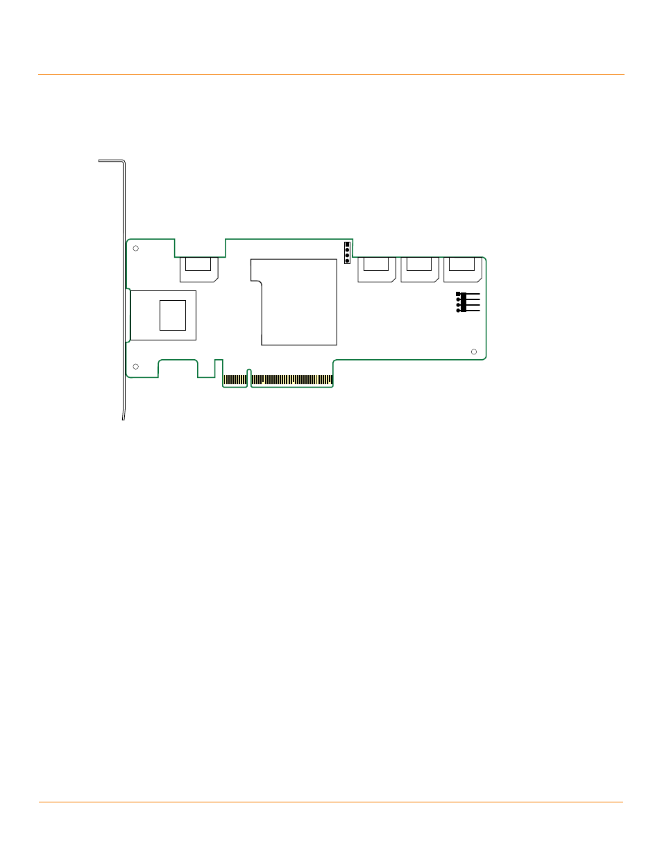
The LSISAS9212-4i4e HBA is a 6.6-in. × 2.7-in. low-profile board. The component height on the top and bottom of the
LSISAS9212-4i4e HBA is in accordance with the PCIe specification.
Figure 6 LSISAS9212-4i4e Board Layout
J1: PCIe x4-lane board edge connector
J12: SFF-8088 mini-SAS, external, right-angle connector
J5, J6, J7, J8: x1, internal 7-pin SATA connectors
J11: 4-pin, right angle, 0.1-in. pitch, pin header for driving external activity LED
J4: UART connection
3.1.6
LSISAS9200-16e HBA Characteristics
The LSISAS9200-16e HBA supports active copper cable and passive copper cable.
3.1.6.1
Memory
The LSISAS9200-16e HBA provides one 2-M × 16-bit Flash ROM for storing the firmware and BIOS, and provides
onboard DDR2 SDRAM.
3.1.6.2
LEDs
The LSISAS9200-16e HBA has two 4-pin headers for external connection of activity LEDs. The LEDs on header J4
correspond to activity on ports 2 and 3, and header J5 corresponds to activity on Port 0 and Port 1.
3.1.6.3
Connectors
This section describes the different connectors on the LSISAS9200-16e HBA. See
PCIe Connector (J10). The LSISAS9200-16e HBA supports a x8 interface. The PCIe host interface connection is
through the edge connector, J10, which provides connections on both the top (J10B) and bottom (J10A) of the board.
The signal definitions and pin numbers conform to the PCIe specification.
J5
J4
J6
J7
J8
J11
J1
J12
Port 0
LSISAS2008
3_00134-03