Avago Technologies Cache Protection for RAID Controller Cards User Manual
Page 30
LSI Corporation
- 30 -
12Gb/s MegaRAID SAS RAID Controllers User Guide
April 2014
Chapter 3: MegaRAID SAS RAID Controller Characteristics
12GB/s MegaRAID SAS RAID Controller Family
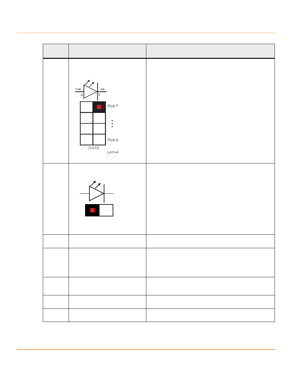
J1A10
Individual PHY and drive fault indication
header
Ports 4 to 7
2x4-pin header
Connects to an LED that indicates whether a drive is in a fault condition.
One LED exists per port. When lit, each LED indicates the corresponding
drive has failed or is in the Unconfigured-Bad state.
The LEDs function in a direct-attach configuration (no SAS expanders
exist). Direct attach is defined as a maximum of one drive connected
directly to each port.
J1A11
Global hard disk drive (HDD) activity LED
header
2-pin connector
Connects to an LED that indicates activity on the drives connected to
the controller.
J1A12
LSI Test header
2-pin connector
Reserved for LSI use.
J1B1
Advanced software options hardware key
header
3-pin header
Enables support for selected advanced features, such as Recovery,
CacheCade, FastPath, and SafeStore disk encryption.
Refer to the MegaRAID Advanced Services Hardware Key Quick
Installation Guide for more information.
J1B2
SAS Port 0 through Port 3 external
connector
One SFF-8644 mini-SAS HD-4e external connector
Connects the controller by cable to an enclosure containing SAS drives
or SATA drives.
J2A1
SAS Port 4 through Port 7 internal
connector
One SFF-8643 mini-SAS HD-4i internal connector
Connects the controller by cable to SAS drives or SATA drives.
J4A1
CacheVault Flash Module (ONFI) interface 80-pin connector
Connects the RAID controller to a flash module.
Table 5 Jumpers and Connectors (Continued)
Jumper/
Connector
Type
Description
B
-$
YH
YH
D
N