Avago Technologies Cache Protection for RAID Controller Cards User Manual
Page 26
LSI Corporation
- 26 -
12Gb/s MegaRAID SAS RAID Controllers User Guide
April 2014
Chapter 3: MegaRAID SAS RAID Controller Characteristics
12GB/s MegaRAID SAS RAID Controller Family
The following table describes the jumpers and the connectors on the MegaRAID SAS 9361-8i RAID controller.
Table 4 Jumpers and Connectors
Jumper/
Connector
Type
Description
J1A2
IPMI-style I
2
C connector for Ports 4 to 7
3-pin connector
Supports SCSI Enclosure Services (SES) over I
2
C through an internal I
2
C
backplane cable.
J1A4
IPMI-style I
2
C connector for Ports 0 to 3
3-pin connector
Supports SES over I
2
C through an internal I
2
C backplane cable.
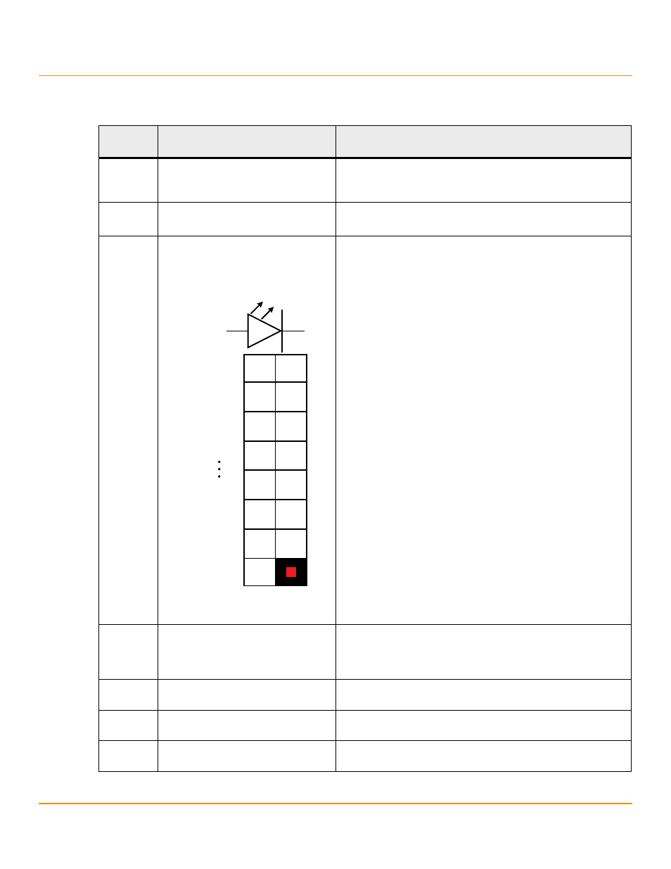
J1B1
Individual PHY and drive fault indication
header
Ports 0 to 3
Ports 4 to 7
2x8-pin header
Connects to an LED that indicates whether a drive is in a fault condition.
One LED exists per port. When lit, each LED indicates the corresponding
drive has failed or is in the Unconfigured-Bad state.
The LEDs function in a direct-attach configuration (no SAS expanders
exist). Direct attach is defined as a maximum of one drive connected
directly to each port.
NOTE The J5A1 connector on the MegaRAID SAS 9361-4i RAID
controller is a single internal port connector.
J2B4
Standard edge card connector
The interface between the RAID controller and the host system.
Along with the PCIe interface, this connector provides power to the
board and an I
2
C interface connected to the I
2
C bus for the Intelligent
Platform Management Interface (IPMI).
J4B1
CacheVault Flash Module (ONFI) interface 70-pin connector
Connects the RAID controller to a flash module.
J5A1
Dual x4 SAS Port 0 through Port 7 internal
connector
Two SFF-8643 mini-SAS HD-4i internal connectors
Connects the controller by cable to SAS drives or SATA drives.
J5B1
LSI Test header
2-pin connector
Reserved for LSI use.
B
-%
3257
3257
YH
YH
D
N