Amprobe AMB-110 Insulation-Resistance-Tester User Manual
Page 32
27
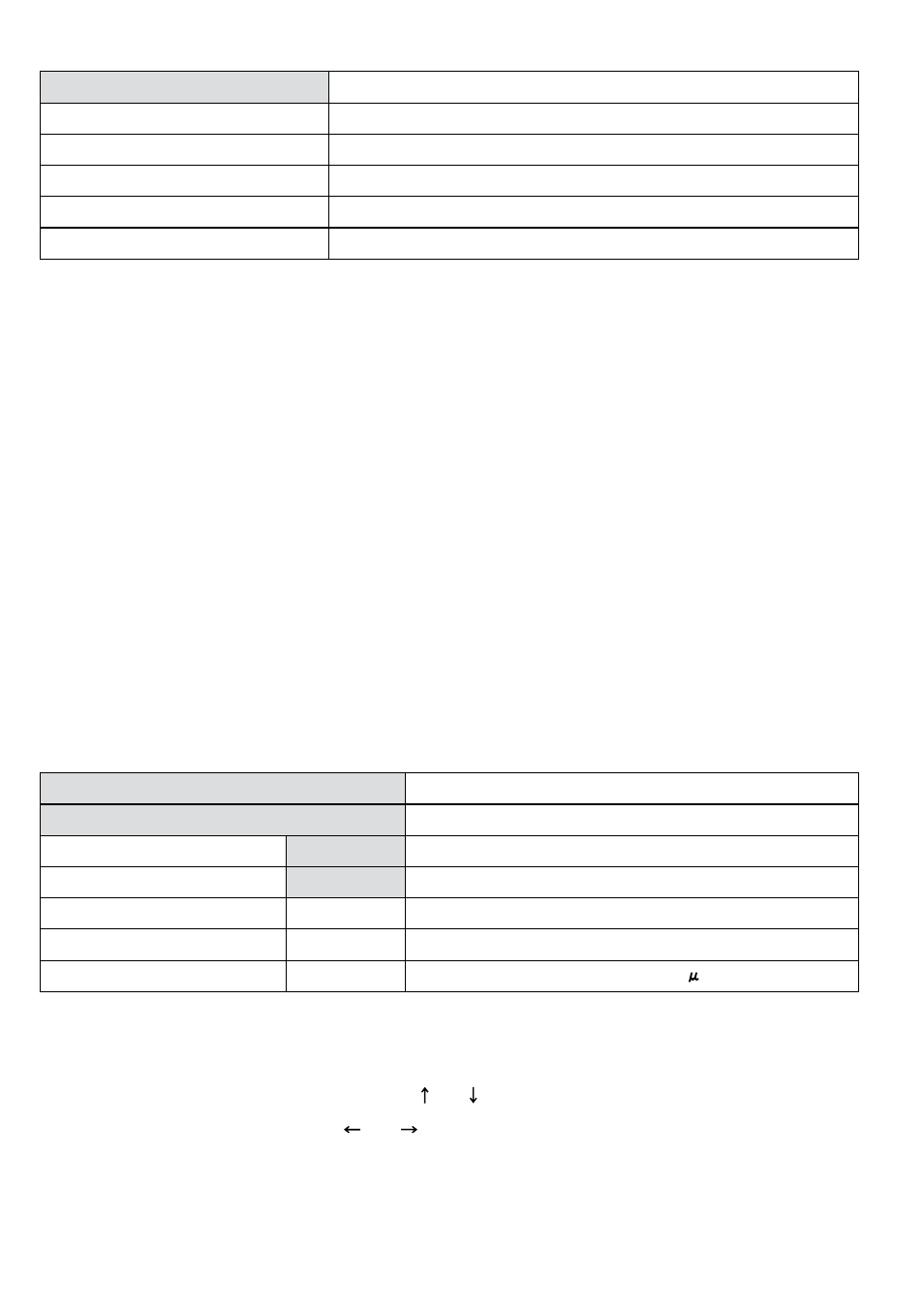
Displayed symbols:
WITHSTANDING VOLTAGE DC
Name of selected function
2000V
Start test voltage
7000V
Stop test voltage
7221V
Actual test voltage – measured value
I=0.002mA
Actual test current – measured value
tm:01min 00s
Timer information
Measuring procedure:
• Connect the test leads to the instrument and to the measured object.
• Press the START/STOP key to start the measurement.
• Wait until the set timers run out or until breakdown occurs, (the result will be displayed).
• Wait for the object under test is discharge.
• The result can be saved by pressing the MEM key twice, see the section of Store, Recall and
Clear Operation.
Note:
• Breakdown is detected when the measured current reaches or exceeds the set current level
trigger.
Notes:
• The timer shows the time needed to complete each step during the measurement and it shows
the total measurement period after the completion of the measurement.
• A high-voltage warning symbol appears on the display during the measurement to warn the
operator of a potentially dangerous test voltage.
Displayed symbols:
WITHSTANDING VOLTAGE DC
Name of selected function
SETTING PARAMETERS:
Ustart
2000V
Start test voltage, step = 25 V
Ustop
7000V
Stop test voltage, step = 25 V
Tstep
00min 00s
Duration of test voltage per one step
Tend
01min 00s
Duration of constant test voltage after reaching stop value
Itrigg
1.500mA
Set trigger leakage current, step = 10 A
Setting up the parameters of Withstanding Voltage DC Test:
• Press the SELECT key, (the set-up menu (Fig. 28) appears on the display).
• Select the parameter) to be set using the and keys;
• Adjust the parameter using the and keys.
• Complete the set-up adjustments by pressing either the ESC key or START key (to run the
measurement directly). The settings displayed last are stored.