Ride height adjustment – SAF-HOLLAND XL-AS11406OM CBX/CB Series Fixed Frame Top Mount Trailer Air Suspension User Manual
Page 12
12
XL-AS11406OM-en-US Rev B · 2012-06-29 · Amendments and errors reserved. © SAF-HOLLAND, Inc.
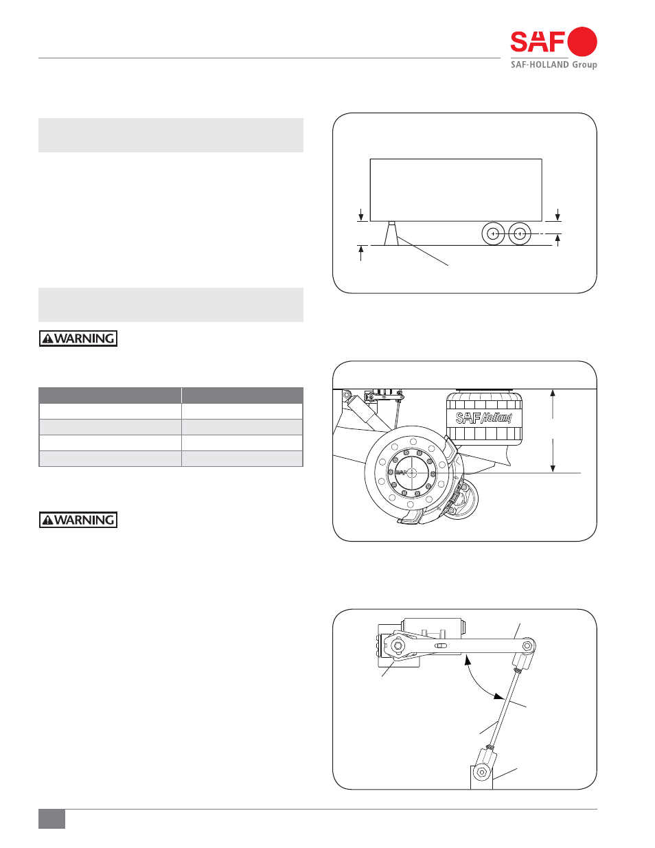
Figure 16
Ride Height Adjustment
Figure 18
12. Ride Height Adjustment
IMPORTANT: Trailer must be unloaded before
beginning any service procedures.
1. On a level surface, support the front of the trailer with
either a kingpin stand, landing gear, or while coupled to
a tractor
(Figure 16).
2. Raise the trailer frame approximately 2" (51 mm) above
the suspension’s specified ride height
(Figure 17).
3. Place multiple jack stands at the suspension’s specified
ride height, see table below, under the vehicle frame at
OEM specified locations, then lower the trailer onto the
jack stands.
NOTE: It may be necessary to shim jack stands to achieve
specified ride height.
Failure to properly support the suspension
during maintenance could create a crush
hazard which, if not avoided, could result
in death or serious injury.
4. Exhaust all air from the suspension, set parking brakes,
and chock the wheels.
Failure to exhaust the suspension air
and chock the tires prior to beginning
maintenance could allow vehicle
movement which, if not avoided, could
result in death or serious injury.
5. Disconnect the linkage from the control arm and lower
axle mounting bracket
(Figure 18).
6. Pin the height control valve so that the valve arm is in
the center or neutral position
(Figure 18).
MODEL
“A” RIDE HEIGHT
CBX/CB-14
14"
CBX/CB-15
15"
CBX/CB-16
16"
CBX/CB-17
17"
4611035"5,*/(1*/
i"w3*%&
)&*()5
'*'5)8)&&-
01&3"5*/()&*()5
¡03-&44
"53*%&
)&*()5
-*/,"(&
$0/530-"3.
)&*()5
$0/530-
7"-7&
-08&3"9-&
.06/5*/(
#3"$,&5
Figure 17
i"w
3*%&)&*()5
$#9'64*0/4)08/