Installation instructions, Suspension assembly installation – SAF-HOLLAND XL-AS11406OM CBX/CB Series Fixed Frame Top Mount Trailer Air Suspension User Manual
Page 11
11
XL-AS11406OM-en-US Rev B · 2012-06-29 · Amendments and errors reserved. © SAF-HOLLAND, Inc.
Installation Instructions
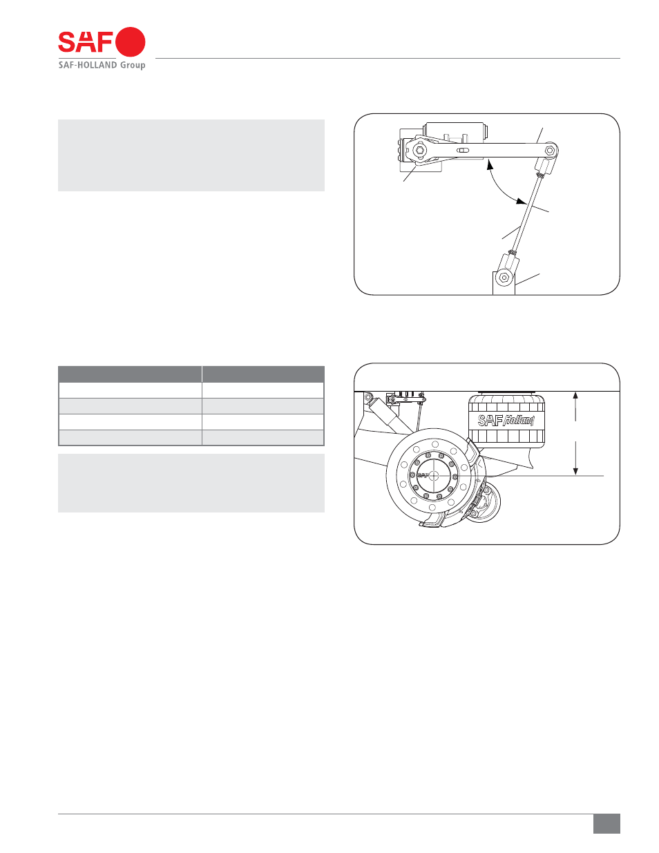
Figure 14
Figure 15
11. Suspension Assembly Installation
NOTE: Locate the suspension on the trailer frame. Refer
to your model’s specific installation drawing for
the proper weld patterns and locations. To obtain a
copy of your specific installation drawing, contact
SAF-HOLLAND Customer Service at 888-396-6501.
1. Once the suspension is correctly positioned, weld the
suspension in place as outlined in Section 9.
2. Ensure the linkage assembled to the height control valve
(HCV) and suspension is installed properly
(Figure 14).
3. Install service and emergency lines to the suspension and
allow the suspension to air up.
6. Measure the ride height of the suspension with a tape
measure
(Figure 15).
7. Compare the measured suspension ride height value to
the appropriate value in the table below. Ensure your
measured ride height value is within ± 1/4" (6 mm).
IMPORTANT: If your measured ride height value is NOT
within ± 1/4" (6 mm), follow the Ride
Height Adjustment procedures described
in Section 12.
4. Visually check all air control system fittings for air leaks
by applying a soapy water solution and checking for
bubbles at all air connections and fittings.
¡03-&44
"53*%&
)&*()5
-*/,"(&
$0/530-"3.
)&*()5
$0/530-
7"-7&
-08&3"9-&
.06/5*/(
#3"$,&5
i"w
3*%&)&*()5
MODEL
“A” RIDE HEIGHT
CBX/CB-14
14"
CBX/CB-15
15"
CBX/CB-16
16"
CBX/CB-17
17"
$#9'64*0/4)08/