Installation continued e1 front panel description – Eton E1 User Manual
Page 7
12
13
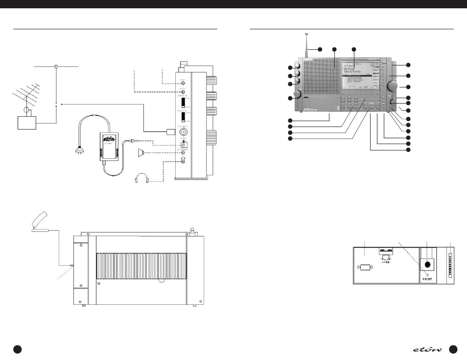
FIGURE 1: E1 INSTALLATION DIAGRAM
INSTALLATION continued
E1 FRONT PANEL DESCRIPTION
E1
MANUAL
Low Impedance Antenna
To Tape Recorder
or Stereo System
From CD or
Tape Player
PAL
Connector
AC
Adapter
TV/FM
Splitter
External
Speaker
Stereo Headphones
XM Radio Home Digital Antenna (Optional)
XM Digital Antenna Jack
(on right side)
REAR VIEW
LEFT VIEW
1
2
3
4
5
6
7
8
20
19
18
17
16
15
14
13
12
11
10
9
1. Squelch
This control allows muting of the receiver’s audio when
no signals are present. Adjust the control until back-
ground noise just disappears when no signal is being
received. An indicator is provided on the display directly
under the signal strength display to show how the
squelch is set relative to received signal strength. (See
the display description starting on page 18). Squelch
also sets the threshold for carrier scan stop. Muting can
be disabled in AUDIO SETTINGS menu, Item 4. However,
carrier stop threshold will be controlled by the Squelch
control regardless of whether or not muting has been
disabled. This control has no effect in XM mode.
2. Treble
This control adjusts the audio frequency response at the
high end of the audio spectrum. Adjust clockwise for
more treble response.
3. Bass
This control adjusts the audio frequency response at the
low end of the audio spectrum. Adjust clockwise for
more bass response.
4. Volume
With the receiver on, adjust this control clockwise to
increase the audio level from the receiver’s speaker or
from headphones. Be certain to set the volume setting
at the desired level for TIMER use.
5. Access Door
Provides access to the battery access panel, to the
microprocessor Reset button access hole, to the Display
21
22
23
Contrast Knob, and to the Factory Programming
Connector. The Factory Programming Connector should
be used only by a factory authorized service center. The
Display Contrast Knob should be adjusted for best dis-
play contrast from the normal viewing position. The
Reset button “reboots” the microprocessor and should
be pressed using a straightened paperclip in the unlikely
event that the receiver exhibits erratic operation,
“freezes”, or displays a flashing “UNLOCK” on the dis-
play. (See the following diagram for the location of
these items).
6. Direct- Key-Input
Numeric Keys - Keys 0 thru 9 plus the ‘.’ key are used to
make direct numeric entries of frequencies, memory
channel numbers, meter band designators, menu selec-
tions, and timer settings.
CLEAR / LOCK - Press this key to clear an incorrectly
entered frequency or other value. Pressing and holding
this key for three seconds will cause the receiver to be
Battery
Access
Panel
Reset
Button
Display
Contrast
Knob
Factory
Programming
Connector