6 grounding and power cable connection, 7 signal input connection – Precision Digital PD540 User Manual
Page 52
Be sure to connect to correct polarities. Connecting to a wrong polarity may cause damage or malfunction.
Use shielded wires and ground the shielding to an independent grounding point.
Keep the input signal and output wiring as far as possible away from the power and ground circuit.
Use a wire w ith low conductive resistance and no three-wire resistance differential.
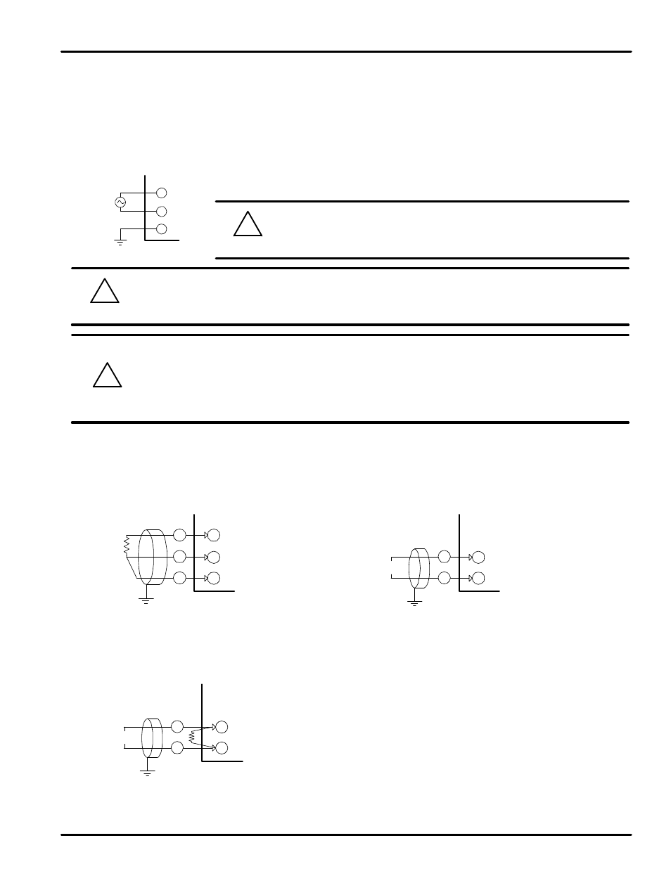
Be sure to connect L (Hot), N (neutral), and GND (ground) as indicated.
Failure to wire the power and ground as indicated could result in damage
to the controller.
To prevent electric shock, be sure to turn off power to the controller and the source circuit breaker before
wiring.
7.6 Grounding and Power Cable Connection
Use a thick grounding cable of at least 2 mm
2
or 14 AWG and shorter than 20 m (approximately 22 ft) for class-3
grounding or better with a grounding resistance of less than 100
Ω .
Be sure to ground from the grounding terminal to an independent grounding point. (1 point grounding)
Use 0.9 to 2.0 mm
2
or 16 AWG vinyl insulated wire (Voltage rating 300VAC) or thicker for power cable connection.
!
CAUTION
7.7 Signal Input Connection
!
CAUTION
!
CAUTION
A
B
b
RTD
INPUT
NOVA
SHIELD
(1) RTD Input
(2) DC Voltage Input
(3) DC Current Input
GND
L
N
-
+
INPUT
NOVA
SHIELD
V
-
+
INPUT
NOVA
SHIELD
DCmA
R
To accept a 4-20 mA signal, select 0.4 to 2.0 VDC input and
connect a 100
Ω resistor across the input terminals as shown.
PD540 Series Nova Digital Process and Temperature Controller
Instruction Manual
52