Operation flow chart – Precision Digital PD540 User Manual
Page 14
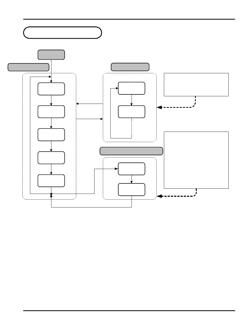
4. Operation Flow Chart
E NT 3 se c
E NT key for
3 seconds or
no keystroke
for 60 se c
Operation Display
Power On
ENT
ENT
ENT
Group display
When setting controller
parameters, G.IN and G.OUT
should be set up prior to any other
parameters.
US1 and US2 are set by the user to
display selected parameters in the
operation display. The parameters
to be displayed are set from
parameters US1 and US2 in
G.CTL. The Table of D-Registers
provides the number to determine
what parameter is displayed by
each. Parameters displayed here
may be altered in this display as
they are normally.
PV Display
'STOP'
ENT
(note 1)
PV Value
SP Value
PV Value
OUT Value
PV Value
H.OUT Value
PV Value
C.OUT Value
US1
US2
G.AT
G.SP
or
User Set Display
(note 2)
(note 3)
(note 4)
(note 5)
(note 6)
(note 7)
'STOP' appears in the SP display when the controller has stopped output operation due to running time
parameters. The Set Point may be changed while in 'Stop' mode.
Operation Display-1 : Initial display after power on. Active Set Point may be set through this menu.
Operation Display-2 : Output control display shows level of output as % of full output scale. May be
set manually if output configured for manual operation.
Heating output display in Heating/Cooling models only.
Cooling output display in Heating/Cooling models only.
Only displayed when User Screen 1 is set in US1.
Only displayed when User Screen 2 is set in US2.
ENT
ENT
ENT
note 1:
note 2:
note 3:
note 4:
note 5:
note 6:
note 7:
See Page 12 for the Group
and Parameter Map
&
PD540 Series Nova Digital Process and Temperature Controller
Instruction Manual
14