Sensor installation – Edelbrock 3530 User Manual
Page 15
15
Pro-Flo EFI Installation Instructions
©2005 Edelbrock Corporation
Rev. 2/05
Brochure #63-0273
Catalog #3530 & #3531
O
2
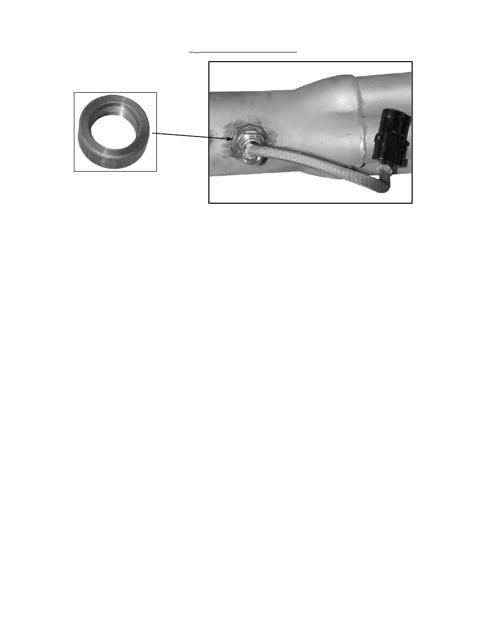
SENSOR INSTALLATION
The exhaust gas oxygen content is determined by the oxygen sensor. The sensor signals the ECU, which compensates when the
air/fuel mixture is either rich or lean.
NOTE: It is recommended that the O
2
sensor installation be performed by a professional muffler shop.
1. Double check header gaskets, replacing if necessary.
2. Drill a 1/2-inch to 9/16-inch hole in the passenger-side header collector reducer, as close to the header collector flange as
possible (1" to 3" away).
NOTE: Before drilling, make sure the O
2
sensor will be mounted horizontally and within reach of the harness connector. Check
to ensure adequate clearance for the sensor, taking into consideration engine movement.
3. Fit the provided fitting into the hole in the exhaust pipe and weld into place.
4. Once it has been welded into place, clean the threads in the center of the fitting. It is important that the threads are clean and
free of paint or ceramic coating, in order to provide a good ground for the O
2
sensor.
5. Thread the O
2
sensor into the fitting. Apply the supplied high-heat anti-seize compound to the sensor threads before installing
the O
2
sensor into the fitting.
NOTE: The O
2
sensor has 18mm x 1.25 spark plug threads.
6. Attach the O
2
sensor to the main system harness. Refer to the MAIN SYSTEM HARNESS section of this manual.
NOTE: UNLEADED FUEL MUST BE USED ONCE THE O
2
SENSOR HAS BEEN INSTALLED.
COATED HEADERS: Use a digital OHM meter to measure the resistance between cylinder head bolt and the nut of the installed
O
2
sensor. The reading should be less than 2 OHMS. If it is more, you need to provide a ground to the O
2
sensor mount.