Gasket surface preparation, Induction system installation – Edelbrock 3530 User Manual
Page 12
12
Pro-Flo EFI Installation Instructions
©2005 Edelbrock Corporation
Rev. 2/05
Brochure #63-0273
Catalog #3530 & #3531
GASKET SURFACE PREPARATION
CAUTION: Replace all gaskets as recommended. We recommend using an OEM style metal pan intake gasket ONLY. Failure to use
a valley pan will result in excessive oil consumption and improper manifold fit. DO NOT use competition type cork or rubber
gaskets, or those that do not include a metal valley pan. Oil and/or coolant leaks may occur with the use of other style gaskets.
1. Remove Fuel rails and Injectors: Fuel injectors and fuel rails are assembled on the manifold and pressure tested. Installing
the intake requires the removal of both fuel rails. Remove the two 1/4" bolts per fuel rail and flat washers. Carefully remove
one fuel rail at a time and any remaining injectors from intake manifold.
2. Check gaskets on head surface and manifold to make sure they fit correctly.
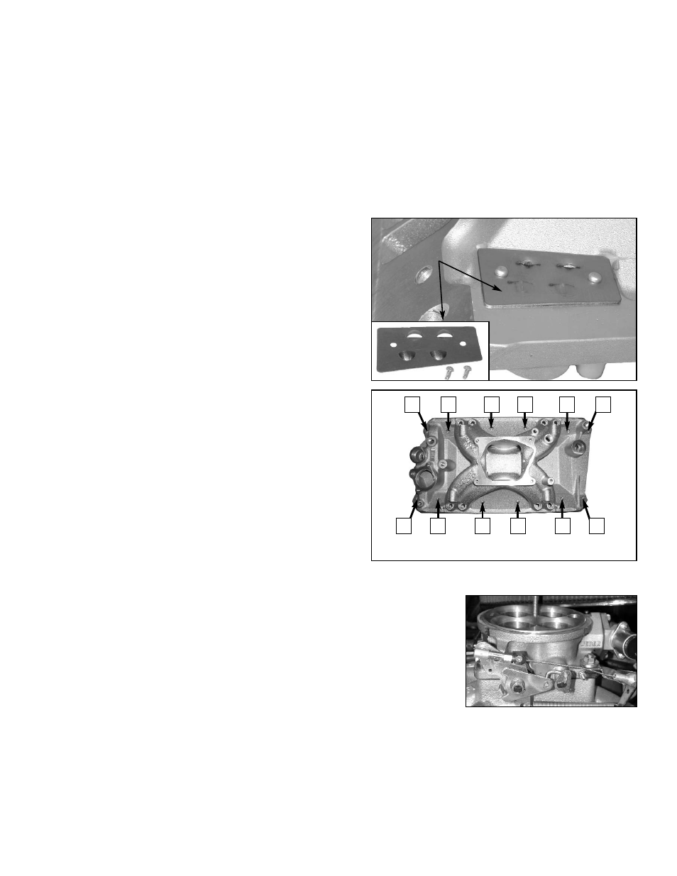
3. Install the supplied PCV baffle plate with the supplied #8 x 3/8”
drive screws. Tap them in gently until flush with the baffle plate.
4. Apply Loctite 598 OEM High Temperature Silicone Gasket around
water passages on head surface.
5. Carefully place the pan gasket on head surface, aligning ports and
bolt holes.
6. Edelbrock recommends the use of Loctite 598 OEM High
Temperature Silicone Gasket instead of end seal gaskets. Apply a
1/4-inch thick bead of sealant across each end seal surface,
overlapping the intake gasket at the four corners.
NOTE: Use the recommended silicon sealer. Others may damage
the O2 sensor. This method eliminates end seal slippage and
deterioration.
7. Apply RTV gasket sealer around water passages on the manifold.
8. Surfaces will become tacky to the touch within a few minutes.
INDUCTION SYSTEM INSTALLATION
1. Carefully position manifold and air valve on engine, centering bolt
holes with the bolt holes in the head.
2. Apply thread sealer or Teflon tape to bolt threads where exposed
to water or oil.
3. Hand tighten all bolts.
4. Torque all manifold bolts to 25 ft/lbs. Torque in the sequence as shown.
5. Install Fuel rails and Injectors: Lubricate injector O-rings (top and bottom) with O-
ring type lubricant before sliding them into fuel rails. Push injectors into rails, making
sure that the electrical connectors on injector bodies face up. Place fuel rail with
pressure regulator on passenger's side with regulator toward rear of engine. Push
down with enough force to seat lubricated O-rings in manifold, making sure not to
damage O-rings. Once installed, secure rails with 1/4" bolts and flat washers to 8 ft-
lbs( 96 In-lbs). When properly installed, the injectors should rotate freely by hand.
6. Re-connect throttle linkage and springs, transmission, cruise control, and fuel lines.
Check all linkage for smooth throttle operation from idle to Wide Open Throttle.
Note: Do not install with a throttle rod, use a cable actuated throttle. Throttle rods will cause
engine surge as the engine moves in its mounts.
7. Re-tighten the valve cover bolts
.
12
Pro-Flo EFI Installation Instructions
6
5
1
4
11
12
8
7
2
3
9
10
Firing Order: 1-8-4-3-6-5-7-2
PCV Baffle
Plate