Kichler 337214 User Manual
Page 4
3
WARNING: This control system is intended for use on 120 volt / 60
Hz power systems ONLY.
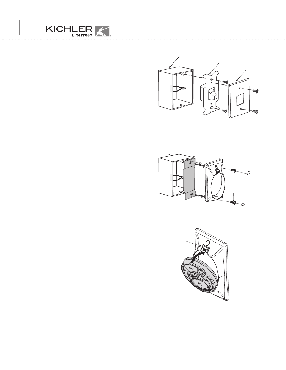
4. INSTALLING THE COOLTOUCH™
CONTROL SYSTEM WALL PLATE
5. STORING THE TRANSMITTER
Place the transmitter in the wall pocket by inserting the bottom of the
transmitter first and then press the top of the transmitter into the pocket.
The transmitter will fully function from this location or you can remove
it to use as a "Hand Held" device.
To remove the transmitter from the wall pocket, push the release button
and the transmitter will fall into your hand.
6. TROUBLESHOOTING GUIDE
If the Ceiling Fan and or light fixture(s) fail to respond to commands from
the transmitter, check the following.
● Check the main power supply and reset or turn on the breaker.
● Make sure the "Receiver Unit" is wired properly.
● Light Fixture pull chain switch turned to ON ?
● Good batteries in transmitter ? Replace if needed.
● Transmitter and Receiver "frequency" switches set to match each
other ?
NOTE: The distance between the transmitter and receiver should not be
greater than 30 feet. For best performance, make sure the Black Antenna on
the end of the receiver unit remains extended and not tangled with any of the
electrical wires.
Select a location to install the Universal CoolTouch™ Control System
Transmitter and Wall Pocket.
RMEMEBER, you can safely use the transmitter outdoors but it should be
mounted indoors away from excess heat and away from contact with water
or humidity.
You can replace an existing wall switch or, install the transmitter wall
pocket on ANY flat surface.
NOTE: The Wall Pocket should be installed with the "Release Button" on
the TOP of the pocket.
Option 1: Install the wall pocket using an existing wall switch outlet box.
Make sure the electrical power is TURNED OFF at the main panel before
continuing.
Step 1. Remove the existing wall plate and the old switch from the wall
outlet box. Wire nut the BLACK leads (hot) together and push back inside
the outlet box. (Fig. H)
Step 2. Install the metal plate and CoolTouch™ Wall Pocket on the existing
wall outlet box using the four screws provided. then place the two plastic
plugs into the wall plate. NOTE: The small plug goes in the TOP hole. (see
figure I)
Option 2: Install the wall pocket on ANY flat surface. Select the desired
location and use the CootTouch™ wall pocket to mark the location for the
mounting holes. Plastic wall anchors and screws are provided for this type
of installation.
After installing the wall anchors, attached the CoolTouch™ wall pocket with
the mounting screws and then insert the plastic plugs to finish the
installation.
Screws
Screws
Plastic plugs
CoolTouch
™
wall pocket
Outlet box
Metal plate
Fig. I
Fig. H
Fig. J
Wall plate
Switch
Outlet box
Release
button