Kichler 10567 User Manual
Kichler Hardware
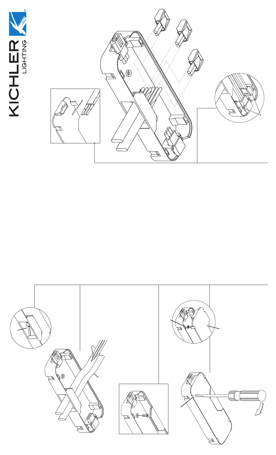
1.
T
u
rn
off po
w
e
r.
NO
TE:
All installations should comply with local
electr
ical codes
. If y
ou ha
ve
an
y doubts concer
ning
installation contact a qualifi
ed licensed electr
ician.
2.
On one side of wire module there are tw
o gates
.
F
eed appro
ximately 5 inches of
T
ype NM non-
metal sheathed cab
le (12 gauge maxim
um)
through
gate
.
NO
TE:
These gates ser
v
e
as str
ain reliefs
holding cab
le securely in place
. Gates should not
be remo
v
ed and no more then one cab
le should
go through each.
3.
P
eel bac
k jac
k
et on cab
le to within one inch of
inside of gate
.
4.
Str
ip appro
ximately 1/2 inch of insulation off each
b
lac
k and white wire
.
NO
TE:
On inside of wire module co
v
e
r is a gauge
to assist in str
ipping the correct amount of
insulation.
5
.
Push str
ipped wires into the appropr
iate connector
:
b
lac
k to b
lac
k
white to white
bare wire to g
reen
Slightly tug on each wire to insure connection has
been made and is secure
.
6.
Push wire module to mounting surf
ace of cabinet
(as close to w
all as possib
le) allo
wing e
xcess
cab
le to f
eed bac
k into w
all.
Secure wire module
in place using pro
vided scre
ws
. It ma
y be necessar
y
to dr
ill 1/16”
maxim
um pilot holes
.
7.
Push wires and connectors inside wire module
.
W
e
suggest pushing each connector to
w
ards a
diff
erent cor
ner of wire module
.
8.
Slip legs on wire module co
v
er into slots inside
wire module and until co
v
er snaps in place
.
NO
TE:
T
o
remo
v
e
co
v
e
r,
slide scre
wdr
iv
er into
slot f
o
rmed b
y
co
v
er and wire module then pull
scre
wdr
iv
er handle a
w
a
y
from wire module until
co
v
er separ
ates from wire module
.
2.
gate
3.
cable
6.
8.
slot
wire module cover
slot
4.
gauge
5.
white/white
black/black
bare wire/green
7.
connectors
IS-10566-US