Figure 3‐15, Аб в – Enterasys Networks A2H124-24FX User Manual
Page 53
Connecting to the Network
SecureStack A2 Installation Guide 3-25
2.
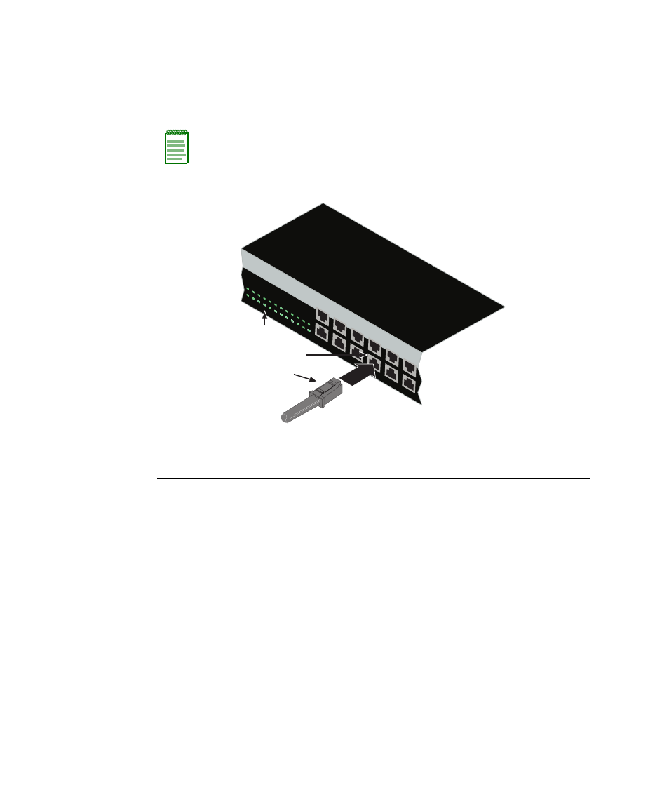
Insert the MT‐RJ cable connector into the MT‐RJ front panel port until it clicks into
place.
Figure 3-15 Connecting a Fiber-Optic Cable Segment to MT-RJ Port
3.
Verify that a link exists by checking that the Link/Activity LED is ON (solid green or
blinking green). If the Link/Activity LED is OFF, perform the following steps until it is
on:
a.
If there are separate fiber‐optic connections on the other device, check the
crossover of the cables. Swap the cable connections if necessary.
b. Verify that the fiber connection meets the dB loss and cable specifications for
multimode cabling, as outlined in the Cabling Guide. Refer to “
” on page xvi for information on obtaining this document.
4.
If a link is not established, contact Enterasys Networks. Refer to “
page 1‐6 for details.
Repeat all steps above until all connections have been made.
Note: To remove the MT-RJ cable connector, press on its release tab and pull it out of the
MT-RJ front panel port.
1 MT-RJ cable connector
3 Front panel Port Link/Activity LED
2 MT-RJ front panel port
1
3
5
7
9
11
13
15
17
19
21
23
2
4
6
8
10
12
14
16
18
20
22
24
2
8
10
12
4
6
1
7
9
11
3
5
А
Б
В