Бг а – Enterasys Networks A2H124-24FX User Manual
Page 37
Installing the Switch on a Flat Surface
SecureStack A2 Installation Guide 3-9
If you are installing several switches in a stack, proceed to “
on page 3‐11. If the switch is being installed as a standalone switch, proceed to
“
Connecting AC and RPS‐SYS Power
” on page 3‐16 for power connection instructions.
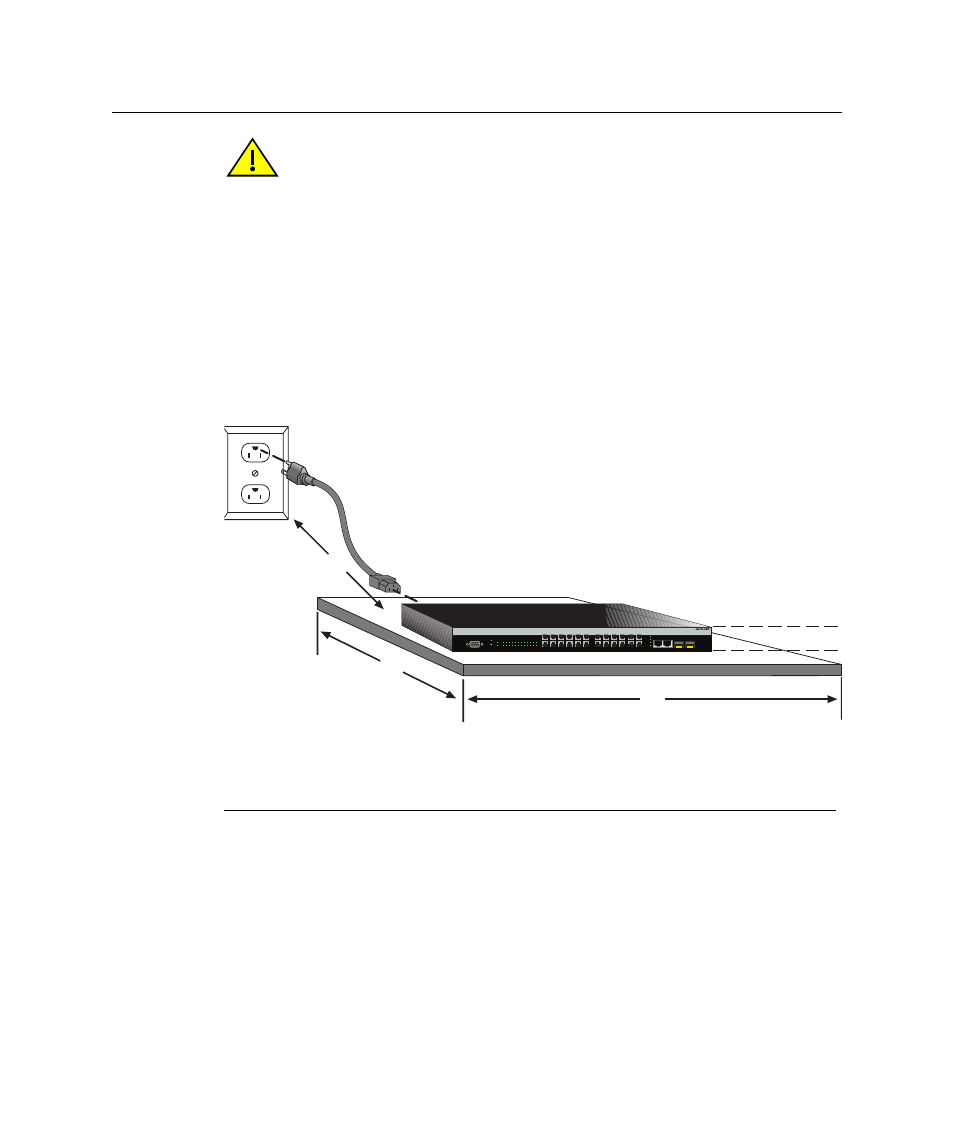
Figure 3-5 Area Guidelines for Switch Installation on Flat Surface
Caution: To ensure proper ventilation and prevent overheating, leave a minimum
clearance space of 5.1 cm (2.0 in.) at the left, right, and rear of the switch.
Do not connect the switch to the AC power source until instructed to do so later in the
installation process.
Precaución: Para asegurar una buena ventilación y evitar que el sistema se
sobrecaliente, deje un espacio mínimo de 5.1 cm (2 pulgadas) con respecto a los lados y
a la parte posterior del aparato.
No conecte el dipositivo a la fuente primaria hasta que no se le indique.
1 Approximately 152 cm (5 ft) from power source
3 44.5 cm (19.4 in.) for proper ventilation
2 4.45 cm (1.75 in.) per switch. (Vertical clearance
depends on number of switches stacked.)
4 41.9 cm (16.5 in.) for proper ventilation
Б
Г
А
Console
CPU
RPS
MGR
1
3
5
7
9
11 13 15 17 19 21 23
2
4
6
8
10 12 14 16 18 20 22 24
25
26
27
28
25/Up
26/Down
Stack
27
28
2
8
10
12
4
6
1
7
9
11
3
5
13
19
21
23
15
17
14
20
22
24
16
18
В