Guidelines for flat surface installation, Guidelines for flat surface installation -8, Chassis bottom, rubber feet placement -8 – Enterasys Networks A2H124-24FX User Manual
Page 36: Figure 3‐4
Installing the Switch on a Flat Surface
3-8 Hardware Installation
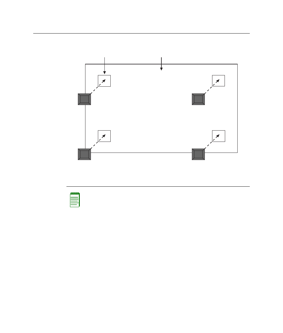
Figure 3-4 Chassis Bottom, Rubber Feet Placement
Guidelines for Flat Surface Installation
Locate the switch within 152 cm (5 ft) of its power source and on a surface as shown in
A temperature of between 0°C (32°F) and 40°C (104°F) must be maintained at the
installation site with fluctuations of less than 10°C (18°F) per hour.
If an optional redundant power system is going to be installed and connected to the
14‐pin Redundant Power Supply input connector on the rear of the switch,
refer to the
installation guide shipped with the redundant power system.
1 Bottom of chassis as seen when chassis is
resting on its back
3 Rubber feet with adhesive backing
(four)
2 Locations to install the rubber feet (four locations)
Note: If a number of switches are being installed in a stack, repeat steps 1 through 4 to
install the rubber feet on each switch before continuing with the installation.
А
Б
В
В
В
В