Connecting stacking cables, Connecting stacking cables -11, Attaching the rackmount brackets -11 – Enterasys Networks A2H124-24FX User Manual
Page 39: Fastening the switch to the rack -11, Ба б а
Connecting Stacking Cables
SecureStack A2 Installation Guide 3-11
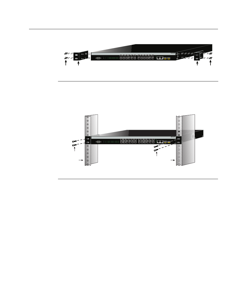
Figure 3-6 Attaching the Rackmount Brackets
2.
With the mounting brackets attached, position the switch between the vertical frame
members of the 19‐inch rack as shown in
. Then fasten the switch securely
to the frame using four mounting screws (user supplied).
Figure 3-7 Fastening the Switch to the Rack
3.
If you are installing this switch in a stacked configuration, repeat this procedure for
each switch until all switches have been installed in the stack, then proceed to
“
” on page 3‐11. Otherwise, proceed to “
Connecting Stacking Cables
The stack of switches can be connected in a closed loop or daisy chained. In a closed loop
all the switches are connected in sequence and the last switch in the stack is connected
back to the first switch. In a daisy chain configuration the cable that would return the
connection back to the first switch in a closed loop is not installed. The advantage of the
closed loop is redundancy, this configuration eliminates any single point of failure. Up to
eight switches can be stacked together and connected by standard UTP Category 5 or
better cables. The stacking cables allow the entire stack to operate with a single IP address.
1 Rackmount brackets
2 M3x6 mm flathead screws
1 Rails of 19-inch rack
2 Mounting screws (supplied by user)
Б
А
Б
А
Console
CPU
RPS
MGR
1
3
5
7
9
11 13 15 17 19 21 23
2
4
6
8
10 12 14 16 18 20 22 24
25
26
27
28
25/Up
26/Down
Stack
27
28
2
8
10
12
4
6
1
7
9
11
3
5
13
19
21
23
15
17
14
20
22
24
16
18
Б
А
Б
А
Console
CPU
RPS
MGR
1
3
5
7
9
11 13 15 17 19 21 23
2
4
6
8
10 12 14 16 18 20 22 24
25
26
27
28
25/Up
26/Down
Stack
27
28
2
8
10
12
4
6
1
7
9
11
3
5
13
19
21
23
15
17
14
20
22
24
16
18