5 e s - u 1 – Emerson 5081-T User Manual
Page 43
37
MODEL 5081-T
SECTION 5.0
DISPLAY AND OPERATION
SECTION 5.0
DISPLAY AND OPERATION
5.1
Displays
5.2
Infrared Remote Controller (IRC) - Key Functions
5.3
Quick Start for Model 5081-T-HT
5.4
Quick Start for Model 5081-T-FF
5.5
Menu Trees
5.6
Diagnostic Messages
5.7
Default Settings
5.8
Security
5.9
Using Hold
CALIBRATE
PROGRAM DIAGNOSE
/ - [ 5 E S - U 1
E X I T
N E X T
E N T E R
#"c""
mS/cm
F
A
U
L
T
H
O
L
D
Appears when transmitter
is in hold (see Section 6.3)
Appears when a disabling
condition has occurred
(see Section 7.3.2)
Active menu: CALIBRATE,
PROGRAM, or DIAGNOSE
Sub-menus, prompts, and
diagnostic messages appear
here
Conductivity value
Units of display
Available commands for sub-
menu, prompt, or diagnostic
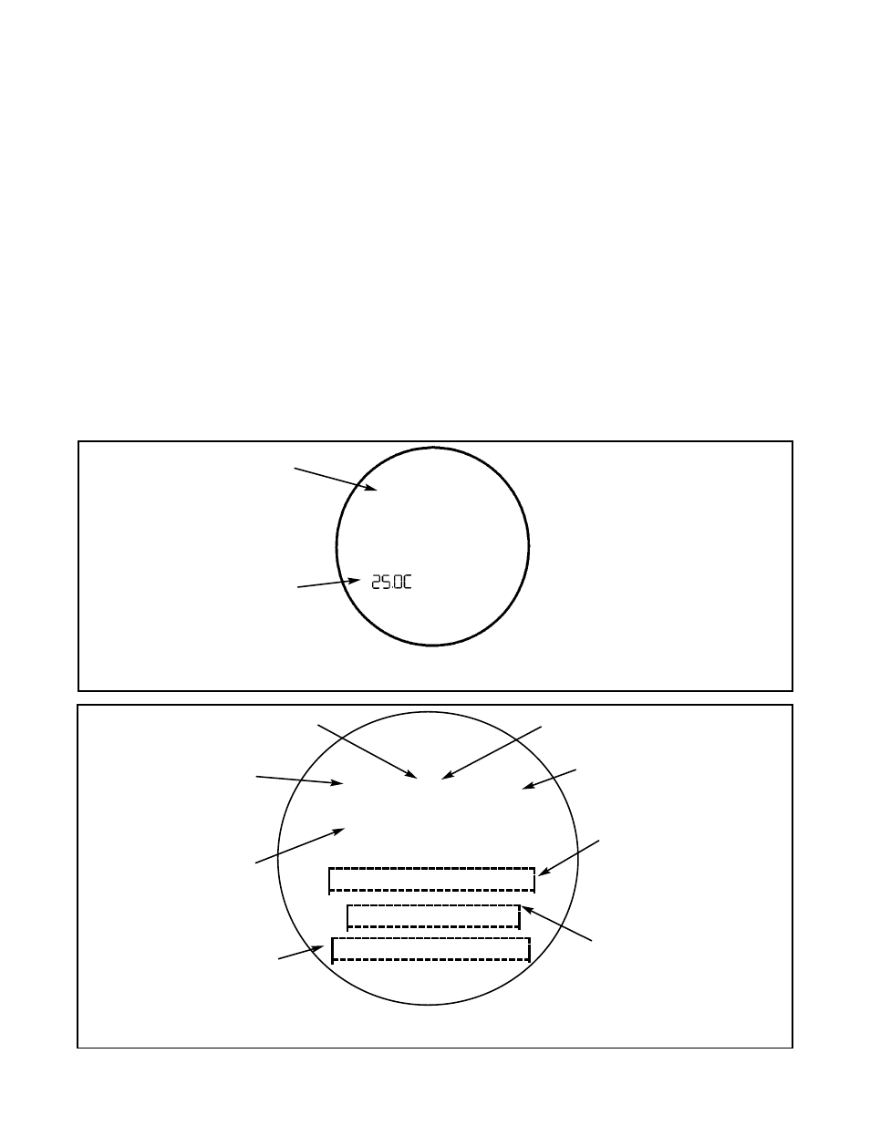
FIGURE 5-2. Program Display Screen
The program display screen appears when calibrating, programming, or reading diagnostic messages.
FIGURE 5-1. Process Display Screen
The process display screen appears during normal operation.
Conductivity value
Temperature in °C or °F
5.1 DISPLAYS
Figure 5-1 shows the process display screen, and Figure 5-2 shows the program display screen.
♥
Indicates HART or F
OUNDATION
fieldbus
digital communications
#"c""
mS/cm