Command tables, Command 1 - channel setup – Casio EA-200 Technical Reference User Manual
Page 5
– 5 –
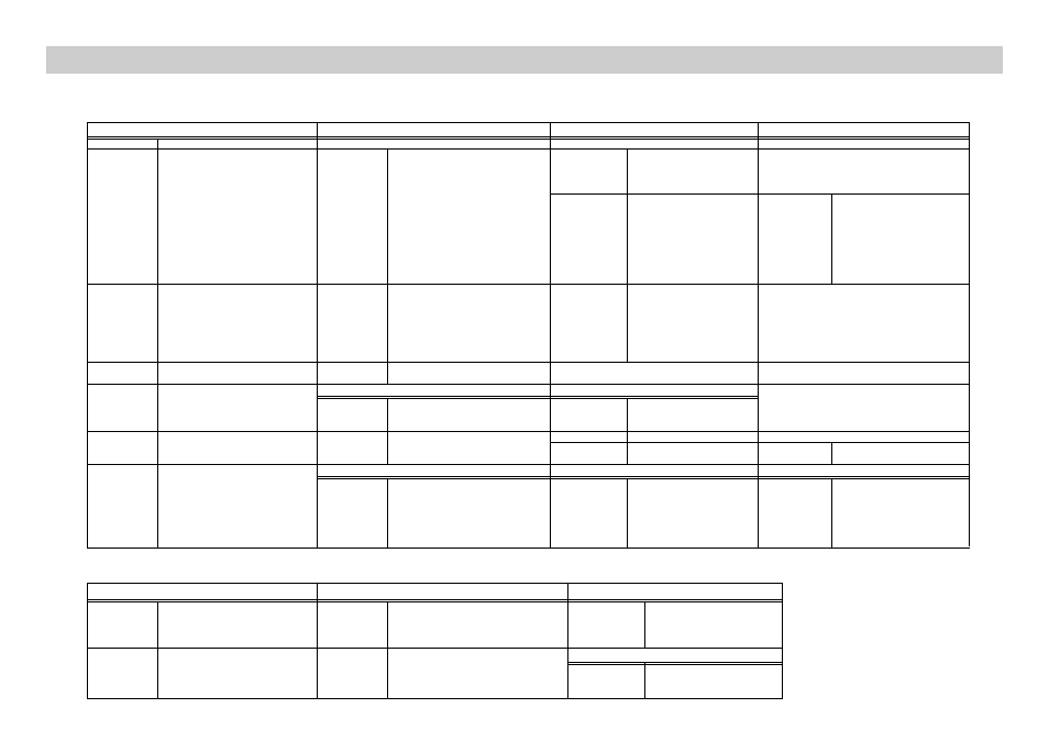
Channel
Operation
Post-Processing
FFT Samples
0
Clear all channels
–––
–––
–––
*1
Channel 1
0
Clear the selected channel.
*0
None
2
Channel 2
*1
Auto-ID
1
d/dt
–––
3
Channel 3
2
Voltage (±10V)
2
d/dt, d
2
/dt
2
(for Voltage probe)
4
Resistance
10
FFT-Real
1 to 13
Samples used
5
Period
11
FFT-Real, Imaginary
(*6)
2
n
(2–8192)
6
Frequency
7
Temperature (Celsius)
8
Temperature (Fahrenheit)
9
Light
10
Voltage (0–5V)
11
Absolute Time
4
SONIC Channel
0
Clear the SONIC channel.
*0
None
*1
Meters
1
d/dt
2
Meters
2
d/dt, d
2
/dt
2
3
Feet
–––
5
Period
6
Frequency
11
Absolute Time
5
DIG IN Port
0
Clear the digital input channel.
–––
–––
*1
Active
6
DIG OUT Port
Data String Output Loops
Data string
0
Clear the digital input channel.
0 to 255
Output data element value
–––
1 to 32
Number of output data elements
(*1)
10
Microphone
0
Clear the Microphone.
*0
None
*1
Active
10
FFT-Real
1 to 13
Samples used
11
FFT-Real, Imaginary
(*6)
2
n
(2–8192)
11
Analog Out CH3 1pin ±3Vout
Data String Output Loops
Data Output Selection
Data string
0
Clear the analog out or speaker.
*0
Data string
±1.5
Output data element value
12
Speaker
1 to 65535
Number of output data elements
(*1)
1
Channel 1
2
Channel 2
3
Channel 3
10
Microphone
Pin No
Trigger Threshold
Trigger Edge (Operation = 5, 6)
*2
1pin Vin (±10V)
±10
Set input voltage threshold value
*0
Rising edge to rising edge
–10 to +10.
1
Falling edge to falling edge
2
Rising edge to falling edge
3
Falling edge to rising edge
10
6pin Vin-low (0–5V)
0 to 5
Trigger Edge (Operation = 11)
*0
Rising edge
1
Falling edge
2
Rising and falling edge
• Channel = 1, 2, 3 or 4, Operation = 5, 6, 11
{ 1, Channel, Operation, Pin No, Trigger Threshold, Trigger Edge }
*: parameter value marked with asterisk are initial defaults.
{ 1, Channel, Operation, Post-Processing, FFT Samples }
Command Tables
• Record Time for Operations 5, 6, and 11
must be 2, 1, and 1 respectively.
• Trigger Source for Channels 1, 2, 3, and 4
must be 2, 3, 4, and 12 respectively.
• Clock Source must be 10.
Command 1 - Channel Setup