Analog sampling, Memory – Casio EA-200 Technical Reference User Manual
Page 3
– 3 –
Analog Sampling
Channel Names: CH1, CH2, CH3
1. CH1, CH2, CH3 Connector Specifications
Pin Number
1
Vin
Ϯ10V (CH3: VinϮ5V and Ϯ3Vout)
2
GND
3
Vres
4
Auto-ID
5
+5.3V DC
6
Vin-low 0–5V
2. Types of Sampling
1 Voltage
Two sampling ranges are shown below.
•
Ϯ10V 1pin (CH3: Ϯ5V)
• 0 to 5V Pin 6
2 Resistance
Two sampling ranges are shown below.
• pin6: 1–100kΩ
• pin4: Auto-ID
3 Pulse period
Two sampling ranges are shown below
•
Ϯ10V 1pin (CH3: Ϯ5V)
• 0 to 5V Pin 6
For details, refer to “Pulse Sampling” on page 4.
Pin 5 +5.3V Power Supply
Supplied from 100 msec before Clock Source.
Variable using power supply command (Command 10).
5pin
Power supplied during ready state.
Sampling Interval
100msec
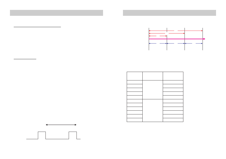
Memory
1. Sampling Time Data
2. Number of Sample Data
Number of Sample Data: 120000
• Number of Sampling Channels and Number of Sample Data
Absolute Time
Relative Time
T2
T3
T4
T2
T3
T4
( T1=0 )
Time Axis
Trigger Source
Sample Value 1
Clock Source 1
Sample Value 2
( T1=0 )
Clock Source 2
Sample Value 3
Clock Source 3
Sample Value 4
* The number of samples is 2^n when FFT Samples (n) is used.
Number of
Sampling
Channels
Clock Source
Maximum
Number of
Sample Data
1
Clock Source =
Timer
120000
2
60000
3
40000
4
30000
5
24000
0
Clock Source =
External Trigger
60000
1
40000
2
30000
3
24000
4
20000
5
17140
The maximum number of
sample data when a timer
is the sampling trigger is
calculated using the
following formula:
120000
Ϭ[Number of
Channels Used]
The maximum number of
sample data when an
external trigger is the
clock source is calculated
using the following
formula:
120000
Ϭ([Number of
Channels Used] + 1)