Communication – Eaton Electrical 9130 User Manual
Page 22
Page 22
9130 UPS-EN
5. Communication
RS 232 and USB Communication Ports
To establish communication between the UPS and a computer, connect your computer to one of
the UPS communication ports using an appropriate communication cable. See Figure 21 for the
communication port locations.
When the communication cable is installed, power management software can exchange data with the
UPS. The software polls the UPS for detailed information on the status of the power environment. If a
power emergency occurs, the software initiates the saving of all data and an orderly shutdown of the
equipment.
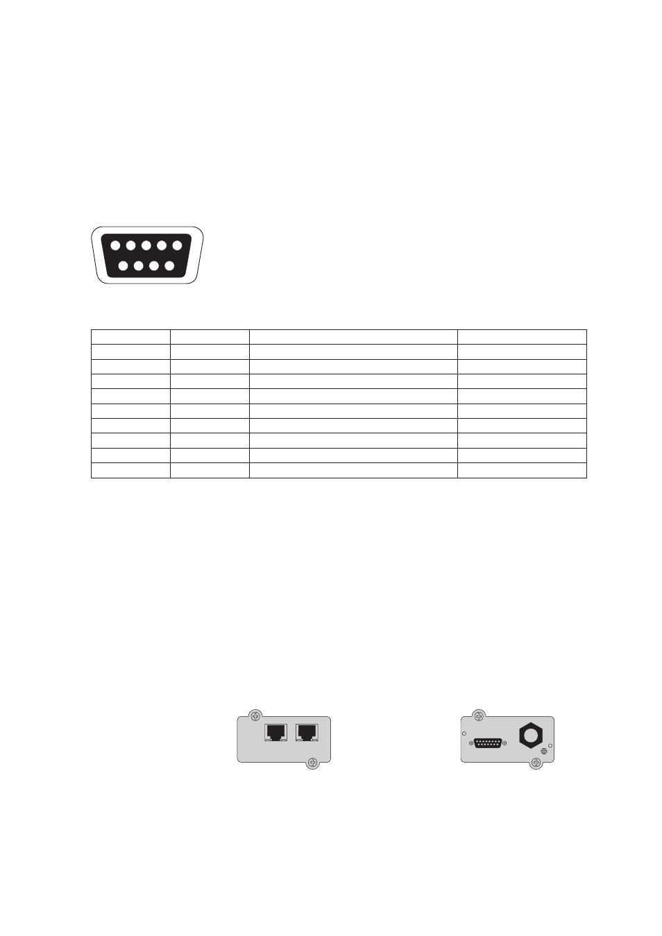
The cable pins for the RS 232 communication port are identified in figure 22, and the pin functions are
described in Table 8.
5
9
8
7
6
4
3
2
1
Figure 22. RS 232 Communication Port (DB-9 Connector).
Table 8. RS 232 Communication Port Pin Assignment
Pin Number
Signal Name
Function
Direction from the UPS
1
DCD
Battery Low signal
(1)(3)
Out
2
RxD
Transmit to external device
Out
3
TxD
Receive from external device
(2)
In
4
DTR
PnP from external device (tied to Pin 6)
In
5
GND
Signal common (tied to chassis)
—
6
DSR
To external device (tied to Pin 4)
Out
7
RTS
No connection
In
8
CTS
On Battery signal
(1)(3)
Out
9
RI
+8-12 Vdc power
Out
(1) Configurable; see the "Relay Configuration" setting in "User Settings" on page 15.
(2) If Pin 3 receives a Low (+V) signal for ≥ 5 seconds, the UPS executes the command selected by the "Signal Inputs" setting in "User
Settings" on page 15.
(3) When the selected condition is active, output signals on Pins 1 and 8 shift from Low (positive voltage) to High (negative voltage). When
the condition no longer exists, the output signal returns to Low.
Connectivity Cards
Connectivity cards allow the UPS to communicate in a variety of networking environments and with
different types of devices. The Eaton 9130 has one available communication bay for the following
connectivity cards:
Connect UPS-MS Web/SNMP Card
- has SNMP and HTTP capabilities as well as monitoring
through a Web browser interface; connects to Ethernet network. In addition, a Environmental
Monitoring Probe can be attached to obtain humidity, temperature, smoke alarm, and security
information.
Relay Interface Card
- has isolated dry contact (Form-C) relay outputs for UPS status: Utility
failure, Low battery, UPS alarm/OK, or On bypass.
See figure 21 on page 21 for the location of the communication bay.
Relay Interface Card
ConnectUPS-MS Web/SNMP Card
ETHERNET
100M
10M
UPS data
Reset
Setting/Sensor
Figure 23. Optional Connectivity Cards.
Remote Power-off
RPO is used to shut down the UPS from a distance. This feature can be used for shutting down the
load and the UPS by thermal relay, for instance in the event of room over temperature. When RPO is
activated, the UPS shuts down the output and all its power converters immediately. The UPS remains
on to alarm the fault.