Operation, English – Eaton Electrical 9130 User Manual
Page 15
Page 15
9130 UPS-EN
ENGLISH
4. Operation
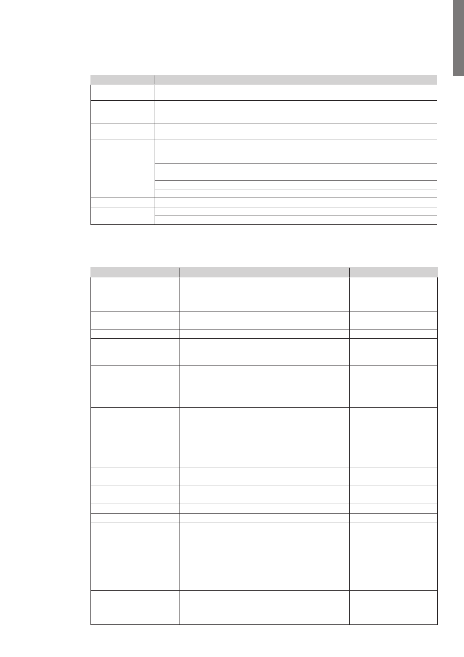
The table 4 shows the basic menu structure.
Table 4. Menu Map for Display Functions
Main Menu
Submenu
Display Information or Menu Function
UPS Status
Main status (mode and load) / Notice or Alarm status
(if any) / Battery status (state and charge level)
Event Log
Displays up to 127 events and alarms.
The Event Log is also available through the serial port. See
"Retrieving the Event Log" on page 19.
Measurements
Load W VA / Load A pf / Output V Hz / Input V Hz / Bypass V Hz /
Input Line Events / Battery V min
Control
Go to Bypass
Transfers the UPS system to internal Bypass mode.
When this command is active, the option changes to "Go to
Normal".
Start Battery Test
Starts a manual battery test.
See "Testing New Batteries" on page 29.
Reset Error State
Clears a "Battery Test Failed" alarm
Restore Factory Settings
Returns all settings to original values
Identification
UPS Type / Part Number / Serial Number / Firmware
Settings
User Settings
See Table 5 for details.
Service Settings
This menu is password-protected.
User Settings
The following table displays the options that can be changed by the user.
Table 5. User Settings
Description
Available Settings
Default Setting
Change Language
[English] [French] [Spanish] [German] [Russian]
Menus, status, notices, and alarms are in all
supported languages. UPS faults, Event Log data,
and settings are in English only.
English
User Password
[Enabled] [Disabled]
If Enabled is selected, the password is USER.
Disabled
Audible Alarms
[Enabled] [Disabled]
Enabled
Set Date and Time
NOTE: time is a 24-hour
clock.
Set Year, Month, Day, Hours, Minutes
Date: yyyy/mm/dd
Time: hh:mm
2008/01/01
12:00
Signal Inputs
Setup: [Not Used] [Force Bypass] [Remote
Shutdown] [Delayed Shutdown]
[On Generator] [Building Alarm 1]
Active: [High] [Low]
See "Programmable Signal Inputs" on page 24.
RS232-3: Not Used, High
cXSlot Serial: Delayed
Shutdown, High
cXSlot Signal: Remote
Shutdown, Low
Relay Configuration
[UPS ok] [On Bypass] [On Battery] [Battery Low]
[Ext. Charger On]
See "Relay Output Contacts" on page 23.
Standard: UPS ok
RS232-1: Battery Low
RS232-8: On Battery
cXSlot-K1: On Battery
cXSlot-K2: Battery Low
cXSlot-K3: UPS ok
cXSlot-K4: On Bypass
Serial Port Configuration
[1200 bps] [2400 bps] [9600 bps]
NOTE: USB communication requires 9600 bps.
RS232: 9600 bps
cXSlot: 9600 bps
Control Commands from
Serial Port
[Enabled] [Disabled]
RS232: Enabled
cXSlot: Enabled
Output Voltage
[208V] [220V] [230V] [240V] [Autosensing]
230 V
Output Frequency
[50Hz] [60Hz] [Autosensing]
Autosensing
Frequency Converter
[Enabled] [Disabled]
If Enabled, the UPS operates as a frequency
converter, with bypass operation and all bypass-
related alarms disabled.
Disabled
Overload Alarm Level
[10%] [20%] [30%] ... [100%]
These values affect alarm level only, not UPS
operation such as transfers or shutdown.
100 %
Generates the Output.
Overload alarm at the set
level.
Transfer to Bypass When
Overload*
[Immediate] [After Delay]
If Immediate, transfer occurs at load > 102 %.
If After Delay, transfer occurs according to table 20
on page 32.
After Delay