Empire Comfort Systems VFHS-20/10T-4 User Manual
Page 23
Page 23
16717-2-0605
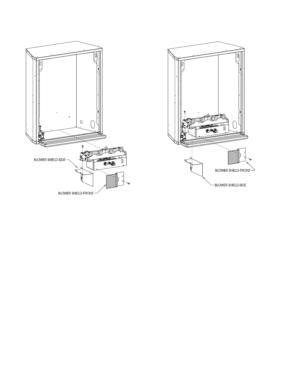
23. Position blower shield side beneath left flange on burner
assembly. Align clearance hole on left flange of burner
assembly with screw hole on blower shield side. Attach burner
assembly to blower shield side with one (1) 10 x 1/2" screw.
(See Figure 3 for not installed or Figure 4 for installed)
24. Remove 8 x 1/4" screw located on left, front of valve cover
on burner assembly. Insert blower shield front adjacent to
blower motor and blower shield side. Align clearance hole
on blower shield front with left, front screw hole on valve
cover. Attach blower shield front to valve cover with 10 x
1/2" screw. (See Figure 3 for not installed or Figure 4 for
installed)
25. For fireplace that is not installed, replace burner assembly
into interior of fireplace.
26. Place inner casing in front of outer casing.
27. Insert inner casing assembly into outer casing.
Figure 4
Figure 3