Wiring – Empire Comfort Systems VFHS-20/10T-4 User Manual
Page 17
Page 17
16717-2-0605
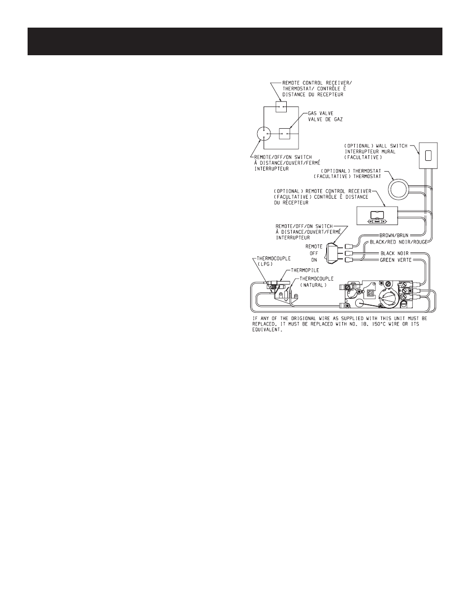
Label all wires prior to disconnection when servicing controls.
Wiring errors can cause improper and dangerous operation. Verify
proper operation after servicing.
Millivolt thermopile is self powered, gas valve does not require
110 volts. Maximum length of 20 feet of 16 AWG to conductor
wires is to be used with all optional switches.
Use the two leads (Brown and Black/Red wires) to attach optional
components.
Check 750 Millivolt System Operation
Millivolt system and all individual components may be checked
with a millivolt meter 0-1000 MV range.
Remote Receiver
Use the following steps to place the remote receiver adjacent to
the gas valve.
Attention: The remote receiver bracket is not used in this
installation.
1. The remote receiver can not be placed behind the gas valve
and burner assembly.
2. When facing the appliance, the remote receiver must be placed
to the right of the gas valve and burner assembly.
Note: Do not let remote control receiver come in contact with
burner assembly.
On circulating vent-free firebox, install remote control receiver
behind bottom louver.
Refer to remote control installation and operating instructions for
more details on remote control.
VFHS-20R Wiring Diagram
Figure 19
.
WIRING