Yaskawa Varispeed-656 DC5 Converter User Manual
Page 11
VS-656DC5 User’s Manual
9 - 20
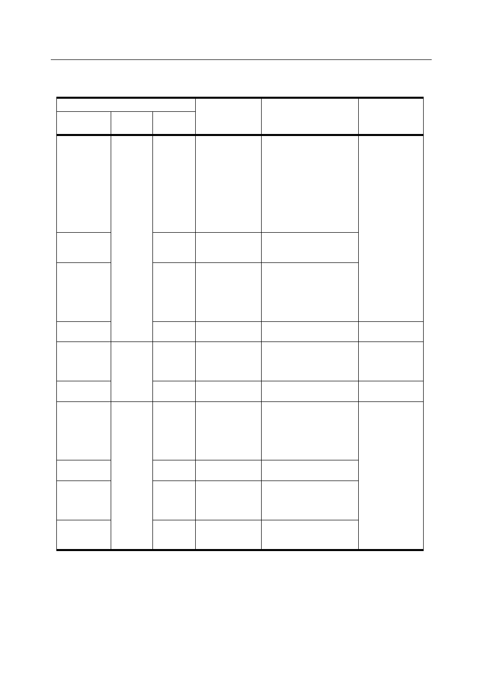
Description of Control Circuit Terminals
(Note) The terminal number indicated is the terminal number of the control card. See the ele-
mentary diagram for the appropriate terminal on the terminal block ITB for wiring
purposes.
Terminals (Note)
Signal Name
Description of Function
Signal Level
Interface
Terminal No.
Name
C Card
Pin No.
9CN
Sequence
Input
17
RUN-SB
Converter operation
starts when “closed”
• This is a one-shot trig-
ger input. Once input
the converter will con-
tinue to run even if
“open”.
• When starting converter
run, terminal number 18
must be “closed”.
24V DC 8mA
photocoupler
insulation
18
STOP
STOP command input nor-
mally closed to run. Con-
verter stops when “open”
19~24
Multi-function
Contact Input
Terminal
The factory settings are
“unused”.
Functions such as fault
reset, external base block,
and external faults can be
set.
25
Sequence Com-
mon
10CN
Photo-
coupler
Output
10, 12,
14, 16
Multi-Function
Open Collector
Output
The factory settings are
“unused”.
Functions for “alarm out-
put”, etc. can be set.
48V DC 80mA
or less
17
Photocoupler
Output Common
TB2
Relay
Output
2, 3
FAULT Output
(Form C Con-
tact)
Output upon error detec-
tion.
Terminal 2: “Open” at
error detection
Terminal 3: “Closed” at
error detection
250V AC 1A or
less
30V DC 1A or
less
1 FAULT
Output
Common
4
Multi-Function
Contact Output
The factory settings are
“unused”.
Functions for “alarm out-
put”, etc. can be set.
5
Multi-Function
Contact Output
Common