5 cn1 i/o – Yaskawa SigmaLogic User Manual
Page 20
4.5 CN1 I/O
4.4.2 Outputs
18
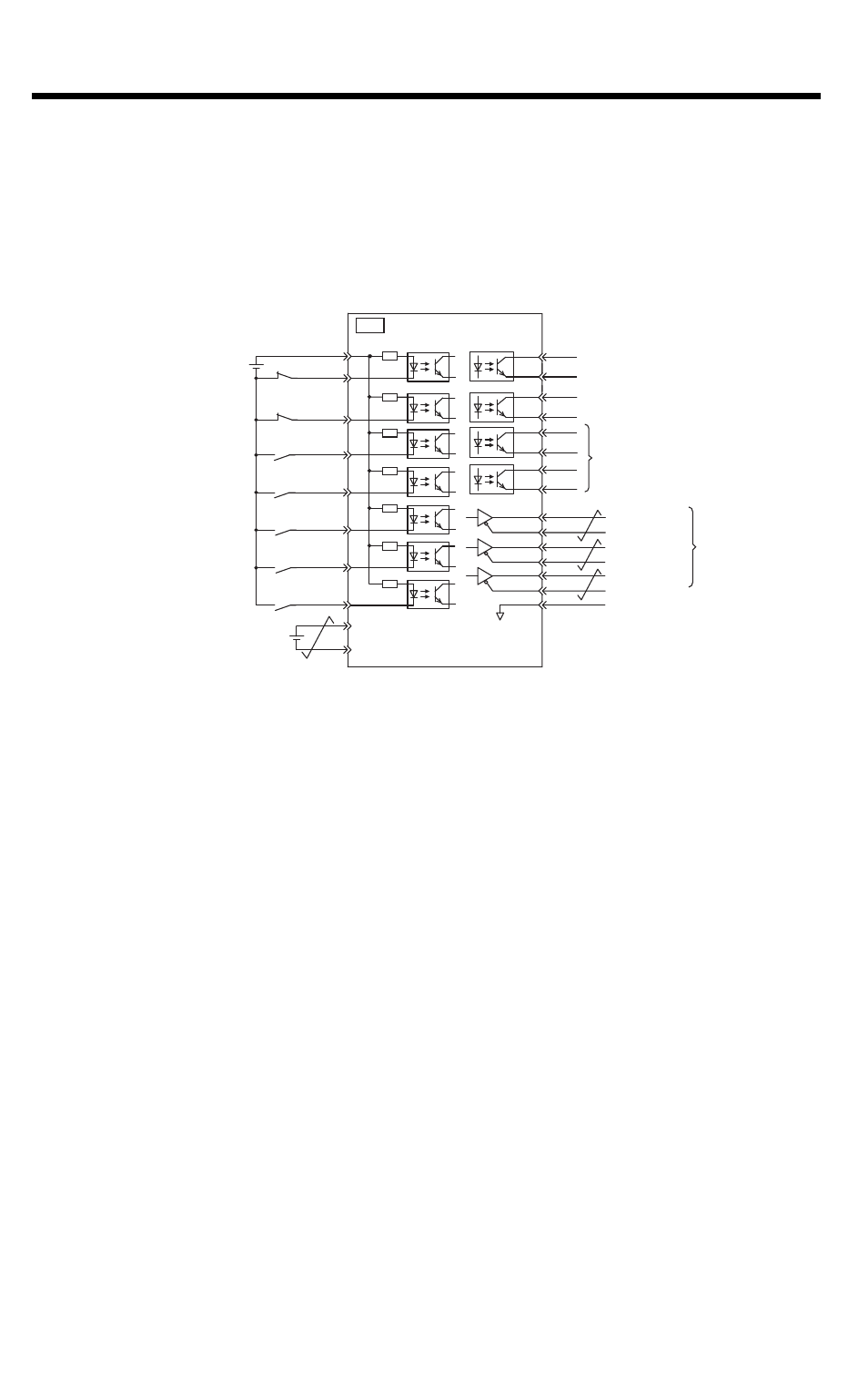
4.5 CN1 I/O
CN1 includes seven digital inputs and three digital outputs that can
be monitored and controlled by the SigmaLogic™.
SO1+ / BK+
SO1- / BK-
/SO2+
/SO2-
/SO3+
ALM+
ALM-
1
2
23
24
3
4
+24V
3.3k
Ω
/SI1
/SI2
/SI3
/SI4
/SI5
6
8
10
9
11
12
/SI6
/SI0
BAT+
BAT-
13
14
15
7
/SO3-
PBO
PCO
/PBO
PAO
/PAO
/PCO
19
25
26
17
18
20
21
22
16 SG
*
1
CN1
Command option
module input 3*
4
Command option
module input 4*
4
Command option
module input 5*
4
Command option
module input 6*
4
Encoder output
pulses phase A
Encoder output
pulses phase B
Encoder output
pulses phase C
General-purpose outputs
General-purpose input 0
Backup battery*
2
(2.8 to 4.5 V)
Reverse run prohibited
(Prohibited when OFF)
Forward run prohibited
(Prohibited when OFF)
Servo alarm output
(OFF for an alarm)
Photocoupler output
Max. operating voltage: 30 VDC
Max. operating current: 50 mA DC
Brake output
(Brake released when ON)
Applicable line
receiver
SN75ALS175
manufactured by
Texas Instruments
or an MC3486
equivalent
Signal ground
Sigma-5 SGDV Servo Amp
Control power supply
for sequence signal*
3
- Tag Generator (30 pages)
- MP3300iec (82 pages)
- 1000 Hz High Frequency (18 pages)
- 1000 Series (7 pages)
- PS-A10LB (39 pages)
- iQpump Micro User Manual (300 pages)
- 1000 Series Drive Option - Digital Input (30 pages)
- 1000 Series Drive Option - CANopen (39 pages)
- 1000 Series Drive Option - Analog Monitor (27 pages)
- 1000 Series Drive Option - CANopen Technical Manual (37 pages)
- 1000 Series Drive Option - CC-Link (38 pages)
- 1000 Series Drive Option - CC-Link Technical Manual (36 pages)
- 1000 Series Drive Option - DeviceNet (37 pages)
- 1000 Series Drive Option - DeviceNet Technical Manual (81 pages)
- 1000 Series Drive Option - MECHATROLINK-II (32 pages)
- 1000 Series Drive Option - Digital Output (31 pages)
- 1000 Series Drive Option - MECHATROLINK-II Technical Manual (41 pages)
- 1000 Series Drive Option - Profibus-DP (35 pages)
- AC Drive 1000-Series Option PG-RT3 Motor (36 pages)
- Z1000U HVAC MATRIX Drive Quick Start (378 pages)
- 1000 Series Operator Mounting Kit NEMA Type 4X (20 pages)
- 1000 Series Drive Option - Profibus-DP Technical Manual (44 pages)
- CopyUnitManager (38 pages)
- 1000 Series Option - JVOP-182 Remote LED (58 pages)
- 1000 Series Option - PG-X3 Line Driver (31 pages)
- SI-EN3 Technical Manual (68 pages)
- JVOP-181 (22 pages)
- JVOP-181 USB Copy Unit (2 pages)
- SI-EN3 (54 pages)
- SI-ET3 (49 pages)
- MECHATROLINK-III (35 pages)
- EtherNet/IP (50 pages)
- SI-EM3 (51 pages)
- 1000-Series Option PG-E3 Motor Encoder Feedback (33 pages)
- 1000-Series Option SI-EP3 PROFINET (56 pages)
- PROFINET (62 pages)
- AC Drive 1000-Series Option PG-RT3 Motor (45 pages)
- SI-EP3 PROFINET Technical Manual (53 pages)
- A1000 Drive Option - BACnet MS/TP (48 pages)
- 120 Series I/O Modules (308 pages)
- A1000 12-Pulse (92 pages)
- A1000 Drive Software Technical Manual (16 pages)
- A1000 Quick Start (2 pages)
- JUNMA Series AC SERVOMOTOR (1 page)
- A1000 Option DI-101 120 Vac Digital Input Option (24 pages)