3 external encoder interface – Yaskawa MP2600iec User Manual
Page 17
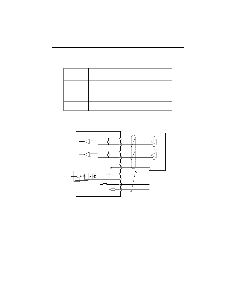
4.3 External Encoder Interface
15
4.3 External Encoder Interface
Two RS-422 compatible inputs are provided for encoder phases A and
B. One position latch input which supports a 5V, 12V, or 24V digital input
signal is provided.
Encoder Input Circuit (PILC refers to positive input side of sensor)
Item
Specification
Number of
channels
One channel (Phase A, Phase B, Index pulse)
Input circuit
Phase A & B: 5V differential input (RS-422 compatible), non-insulated.
Maximum frequency 4MHz.
Index pulse: 5V/12V/24V photo coupler input. Maximum frequency
500kHz (pre-quadrature. This signal is used for external encoder latch.
Counter modes
Quadrature, pulse and direction, up/down
PIL Latch input
Hardware latency: 5
s or less, sinking input
DI_01 Latch Input
Hardware latency: 600
s or less, sinking input
R
4
5
+5V
0V
Phase A
Pulse generator
R
29
30
+5V
0V
Phase B
6
PB+
PB-
PA+
PA-
GND
35
PIL
R
9
PILC(5V)
34
10
R
R
+5V
R
GND
31
PILC(12V)
PILC(24V)
CN13 Connector
- Tag Generator (30 pages)
- MP3300iec (82 pages)
- 1000 Hz High Frequency (18 pages)
- 1000 Series (7 pages)
- PS-A10LB (39 pages)
- iQpump Micro User Manual (300 pages)
- 1000 Series Drive Option - Digital Input (30 pages)
- 1000 Series Drive Option - CANopen (39 pages)
- 1000 Series Drive Option - Analog Monitor (27 pages)
- 1000 Series Drive Option - CANopen Technical Manual (37 pages)
- 1000 Series Drive Option - CC-Link (38 pages)
- 1000 Series Drive Option - CC-Link Technical Manual (36 pages)
- 1000 Series Drive Option - DeviceNet (37 pages)
- 1000 Series Drive Option - DeviceNet Technical Manual (81 pages)
- 1000 Series Drive Option - MECHATROLINK-II (32 pages)
- 1000 Series Drive Option - Digital Output (31 pages)
- 1000 Series Drive Option - MECHATROLINK-II Technical Manual (41 pages)
- 1000 Series Drive Option - Profibus-DP (35 pages)
- AC Drive 1000-Series Option PG-RT3 Motor (36 pages)
- Z1000U HVAC MATRIX Drive Quick Start (378 pages)
- 1000 Series Operator Mounting Kit NEMA Type 4X (20 pages)
- 1000 Series Drive Option - Profibus-DP Technical Manual (44 pages)
- CopyUnitManager (38 pages)
- 1000 Series Option - JVOP-182 Remote LED (58 pages)
- 1000 Series Option - PG-X3 Line Driver (31 pages)
- SI-EN3 Technical Manual (68 pages)
- JVOP-181 (22 pages)
- JVOP-181 USB Copy Unit (2 pages)
- SI-EN3 (54 pages)
- SI-ET3 (49 pages)
- MECHATROLINK-III (35 pages)
- EtherNet/IP (50 pages)
- SI-EM3 (51 pages)
- 1000-Series Option PG-E3 Motor Encoder Feedback (33 pages)
- 1000-Series Option SI-EP3 PROFINET (56 pages)
- PROFINET (62 pages)
- AC Drive 1000-Series Option PG-RT3 Motor (45 pages)
- SI-EP3 PROFINET Technical Manual (53 pages)
- A1000 Drive Option - BACnet MS/TP (48 pages)
- 120 Series I/O Modules (308 pages)
- A1000 12-Pulse (92 pages)
- A1000 Drive Software Technical Manual (16 pages)
- A1000 Quick Start (2 pages)
- JUNMA Series AC SERVOMOTOR (1 page)
- A1000 Option DI-101 120 Vac Digital Input Option (24 pages)