Memory map – Yaskawa MP2300 User Manual
Page 2
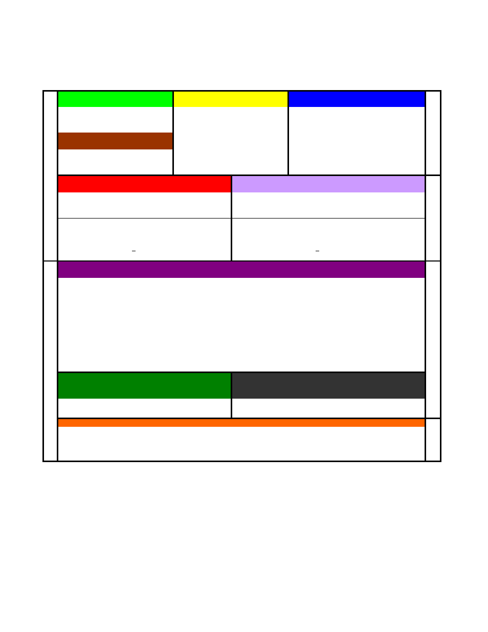
MP2300 Quick Reference Guide Rev1.5
5.5 MB Stores ladder drawings, Local registers and special tables
S
(Global)
SW0000-1023
C
(Global)
M
(Global)
(MW00000-65535)
System information and status (read only)
Constant, Read only registers.
General Multi-Purpose read/write registers
Example: Flicker relays, Calendar,
User Free: MW00000-29999
Scan time setting, error codes, ect.
Convention:
Axis#1:MW1000-1999, Axis#2:MW2000-2999
Fixed Parameters
(for each axis)
Example:
*Function Block RDA: MW30000-65535
Written to in Module Configuration
Mechanical system specifications
Axis#1:MW30100. Offset=200 per axis
Define axis units, motor specs.
(pulley ratios, encoder counts per load rev)
Master-Slave: MW56000. Offset=50 per M-S Pair
Cannot be written by ladder
Reference: RDA Spreadsheet
Changes usually require power cycle
Reference:
* If using motion function blocks.
I (Input)
IW0000-FFFF
O (Output)
OW0000-FFFF
general purpose & motion data (Read only by application program)
general purpose &motion data (Read/Write by application program)
Physical Inputs: IW0000-7FFF
Physical Outputs: OW0000-7FFF
Convention:
IW0410+ for Local I/O modules
Convention:
OW0410+ for Local I/O Modules
IW0010+ for M-LINK I/O modules
OW0010+ for M-LINK I/O modules
Axis (Motion) Input: IW8000-807F (Module#1, Axis#1) Axis (Motion) Output: OW8000-807F (Module#1, Axis#1)
"motion monitoring"
Offset
80h per axis
"motion setting"
Offset
80h per axis
800h per module
800h per module
Example:
IB8000 0 = controller ready
Example:
OB8000 0 = turn servo on
Reference:
Basic Module User Man 7.2.3
Reference:
Basic Module User Man 7.2.2
D (Local Registers)*
Used as general purpose read/write in the defined Drawing only.
Suggested
Bits: DW00000-00008
(DB000000~DB00008F)
Convention:
One-Shot
DW00009
(DB000090~DB00009F)
Word Operations:
DW00010-00025
(16-bit integers)
Accumulators:
DW00026
(16-bit Integer accumulator)
DW00027
(16-bit Logic [Hexadecimal] Accumulator)
DL00028
(32-bit Long Accumulator)
DF00030
(32-bit Floating point Accumulator)
Long & Float
DW00032-00098*
F.B. Work Register: DW00100-00320*
*Default is 32 D-registers per drawing. R-click drawing in File Manager - increase to 320 when using Function Blocks.
Reference:
#
("Sharps")
#W00000-16383
Module Configuration
Drawings:
H, L, A, I
H (High Scan)
Use for all code that runs motion related functions
L (Low Scan)
Use for code that runs HMI, or user operated switches, lights, etc
A (Startup)
Use for drawings that should automatically run once at controller power up.
I (Interrupt)
Use to run a special interrupt routine after receiving a local input defined as a dedicated "Interrupt."
D
E
C
I
M
A
L
H
E
X
A
D
E
C
I
M
A
L
Data that end user can change in MPE720
without needing to access the drawings.
D
E
C
I
M
A
L
(32-bit Integers, 32-bit Floating Point)
(Bits, integers, floats as defined in Function Block)
Local Constants. General purpose, read-only by the specifed Drawing
they are defined in.
Each hardware module on the rack has several configuration files. This data
is stored in program memory.
Set up via a table in the "properties" dialog box for each
drawing. Rarely Used
New project requires setting Module Configuration first. Select
from File Manager under Definition Folder"
MP2300 Memory Map
R
e
g
ister M
e
m
o
ry
(B
attery B
a
ckup)
Pr
ogr
a
m
Me
mor
y (O
verw
ritten from
F
L
A
S
H
at pow
er up)
Page 2 of 14