Vertical termination (continued) – Empire Comfort Systems DVX36DP31 User Manual
Page 38
25613-0-0309
Page 38
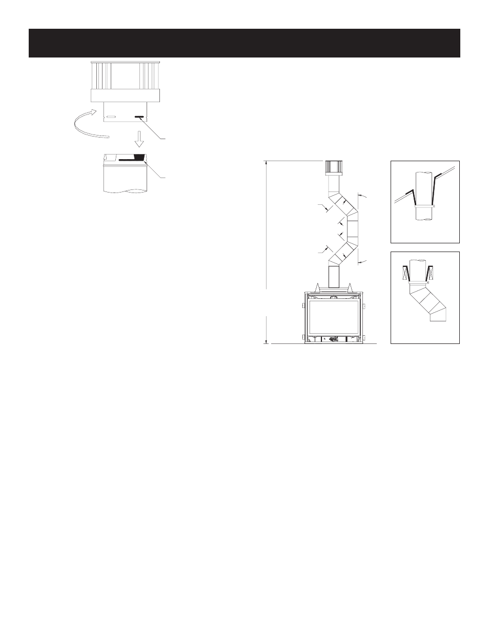
Vertical Through the Roof Applications (Figure 62)
Your Gas Fireplace has been approved for:
a) Vertical installations up to 40 feet in height.
b) Two sets of 45 degree elbow offsets within these vertical
installations. From 0 to a maximum of 8 ft. a vent pipe can be
used between elbows.
c) Wall straps must be used to support offset pipe every 4'.
This application will require that you first determine the roof pitch
and use the appropriate venting components.
Figure 62
Figure 61
CAUTION: Treatment of firestop spacers and construction of
the chase may vary with the type of building. These instructions
are not substitutes for the requirements of local building codes.
Therefore, your local building codes must be checked to determine
the requirements for these steps.
NOTE: When installing this vent system in a chase, it is always
good building practice to insulate the chase as you would the
outside walls of your home. This is especially important for cold
climate installations. Upon completion of building your chase
framing, install the vent system by following the instructions in
this manual. Remember to build the chase large enough so that
minimum clearance of combustible materials (including insulation)
to the vent system are maintained.
Reassembly and Resealing Vent Pipe System
Attach vent pipe to inlet and outlet vent adaptor on fireplace,
replace horizontal and vertical pipe lengths, elbows and horizontal
or vertical termination kit.
All vent system components lock into place by sliding the concentric
pipe section with four (4) equally spaced interior beads onto the
appliance collar or previously installed component end with four
(4) equally spaced indented sections. When the internal beads of
each starting outer pipe line up, rotate pipe section clockwise 90°
(approximately 3 inches). The vent pipe is now locked together.
Continue replacing components per the vent system configuration.
Be certain that each succeeding vent component is securely fitted
and locked into the preceding component in the vent system.
Reassembly and Resealing Gas Accumulation Relief System
Glass Frame Assembly and Combustion Chamber
Whenever the glass frame assembly is pivoted open by a delayed
ignition in the main burner, the glass frame assembly gaskets and
combustion chamber must be examined by a qualified service person
for damage. All damaged gaskets on the glass frame assembly and
combustion chamber must be replaced by a qualified service person.
If damage occurs to the combustion chamber, it must be replaced
by a qualified service person. Contact Empire Comfort Systems,
Inc. for replacement parts.
TYPICAL ROOF
SUPPORT
TYPICAL JOIST
SUPPORT
40’
(12.19M)
MAXIMUM
8’ (2.44M)
MAXIMUM
8’ (2.44M)
MAXIMUM
45°
45°
VERTICAL TERMINATION (continued)
FEMALE
LOCKING
LUG
MALE
LOCKING
LUG