15 connecting the rly out connector, Rly out connector specifications, Rly out connector connection cable – Yaskawa MP3300iec User Manual
Page 26: Rly out connector connection example
26
YASKAWA America, Inc. MP3300iec Hardware Manual YAI-SIA-IEC-7
15 Connecting the RLY OUT Connector
15
Connecting the RLY OUT Connector
The RLY OUT connector connects the status output terminal. It is a normally open contact relay output. The RLY OUT
connector is linked to the operation of the RDY indicator: The contacts close when the indicator lights, and they open
when the indicator goes out.
Note: When the RDY indicator is lit, the Controller is operating normally. It does not necessarily mean that the user programs are being
executed.
RLY OUT Connector Specifications
The operation of the RLY OUT connector is linked to the operation of the RDY indicator on the CPU Unit.
RDY indicator lit: Circuit closed
RDY indicator not lit: Circuit open
Contact Ratings
RLY OUT Connector Connection Cable
To connect the RLY OUT connector, use a cable with a wire size of AWG 28 to AWG 14 (0.08 to 2.0 mm
2
) and a
maximum outer diameter of 3.4 mm.
The procedure to make the RLY OUT connector cable is the same as for the 24-VDC power supply cable.
Note: You can use the RLY connector on the Power Supply Unit only on the Rack to which the CPU Unit is mounted. On Racks without
the CPU Unit, the power supply circuit is always open.
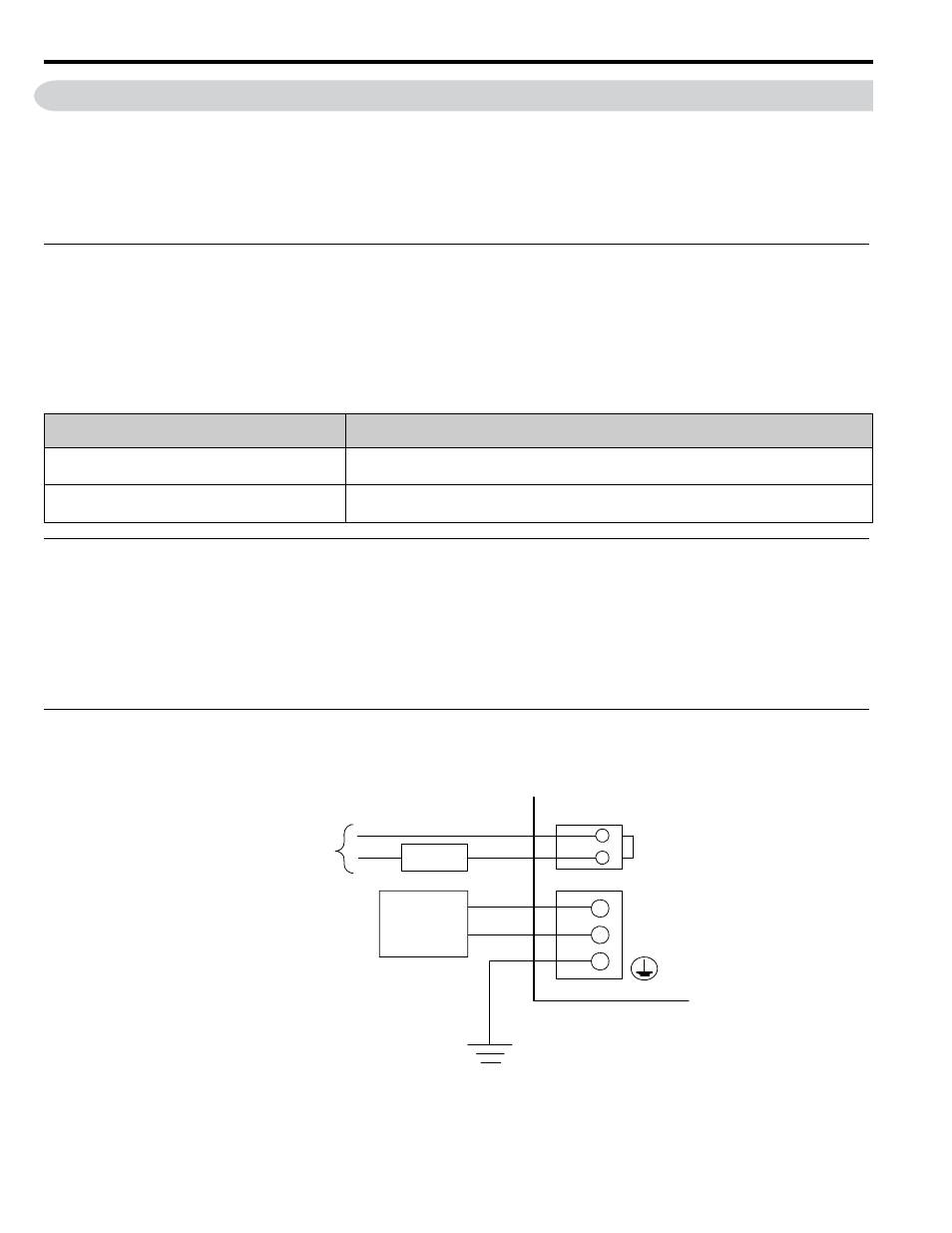
RLY OUT Connector Connection Example
Refer to the following figure for an example of connecting the RLY OUT connector.
Input
Voltage
Current Capacity
24 VDC
0.5 A (resistive load)
0.25 A (inductive load)
125 VAC
0.4 A (resistive load)
0.2 A (inductive load)
RLY OUT
24 VDC
0 VDC
POWER
Ground to 100
Ω max.
24-VDC
power supply
Power
supply
Error: OFF
Normal operation: ON
RLY OUT output